Connecting Rods

Following,  is the connecting rod construction.
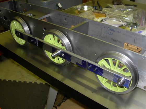
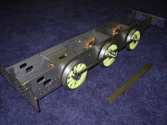
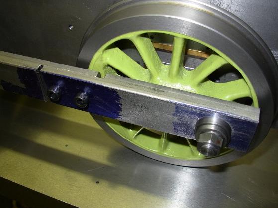
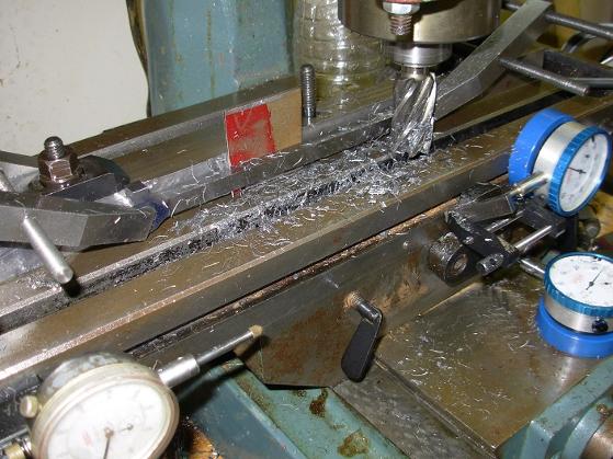
Before making the connecting rods. I made a temporary rod to confirm the center distances of all three axles.
Another temporary rod was made for the other side.
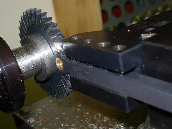
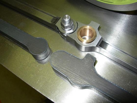
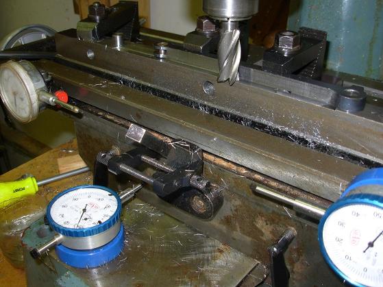
After the crank pin holes were established in the rods, the ends were slotted and finished.                  
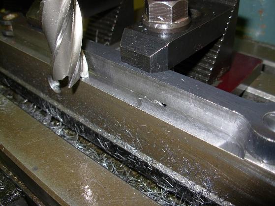
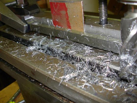
The sides of the rods were machined to size.          
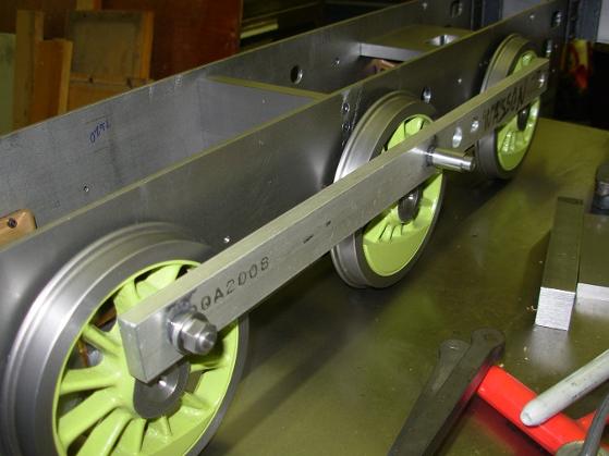
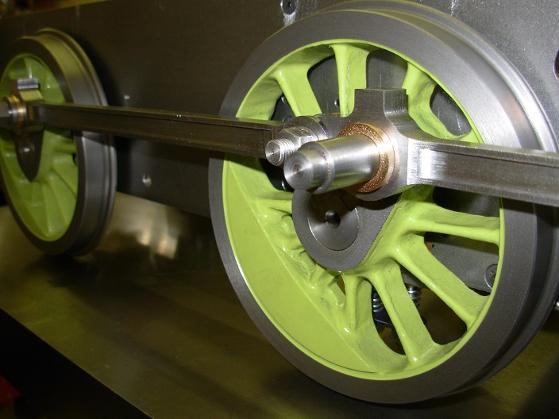
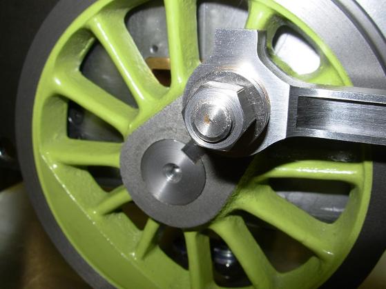
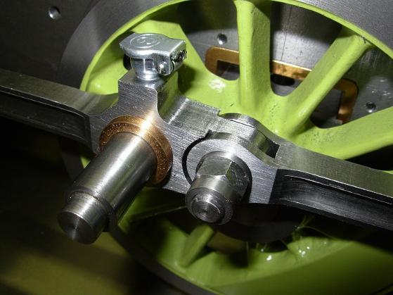
The rods in place to check for fit.
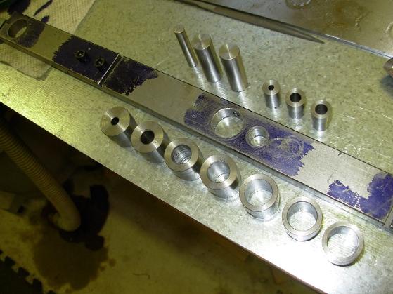
Finished rods next to theraw, unmachined, laser cut rod blanks.
The temporary rod was adjustable. It was also to be used as a drill jig for positioning the crank pin holes in the rods.
The adjustable rod was fitted with drill bushings of various sizes to finish the holes in the rods.  
The rods were slotted in the lathe with a cutter in the head stock, and the rod held in the tool holder. 
 As I have no DRO, several dial indicators were used  as travel stops.
 
Rod with oil cup installed.