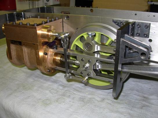
Cross Head & Valve Gear
Following, is the cross head and valve gear construction. Lots of photos!
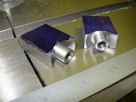
The crossheads start as two little blocks of steel.
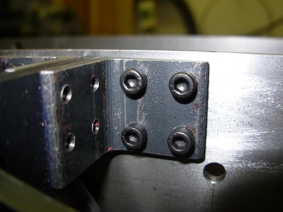
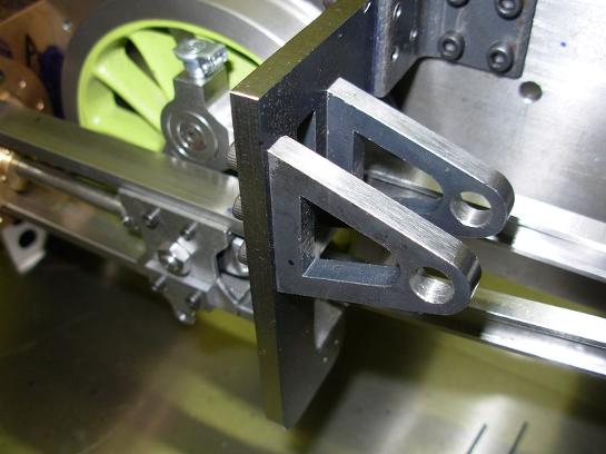
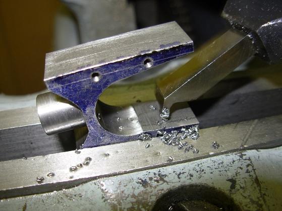
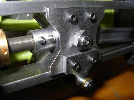
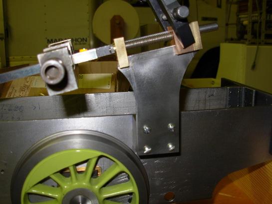
One of the mouting brackets for the motion plate.
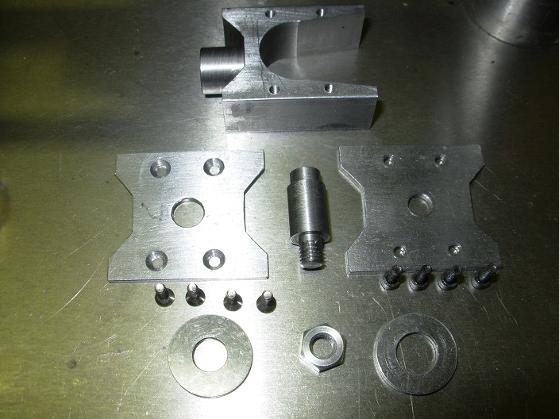
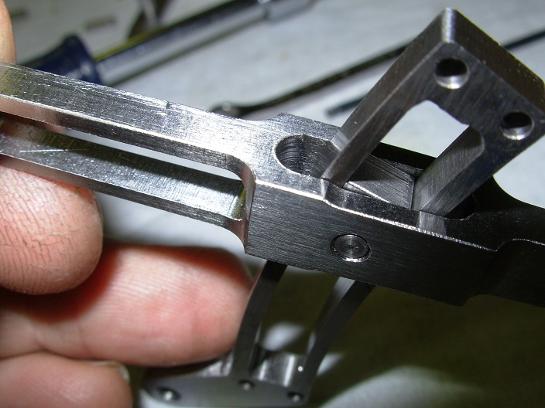
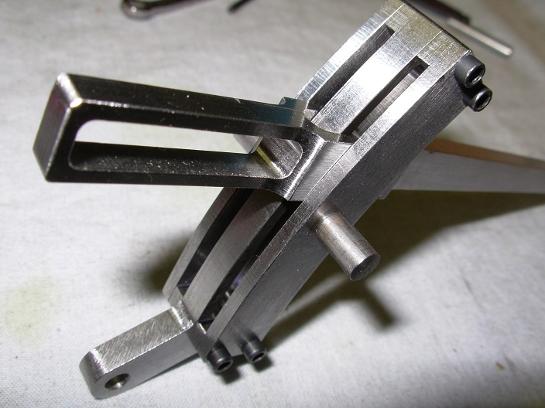
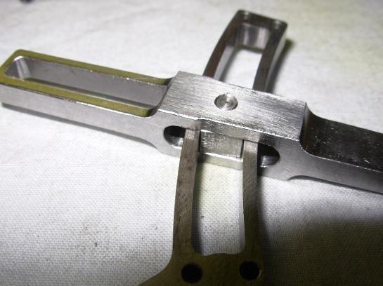
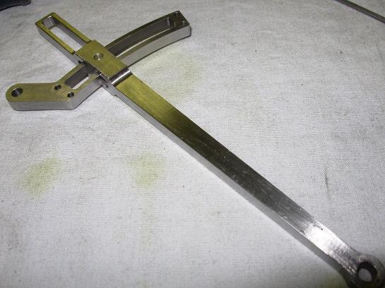
Here are the pieces for the cross head.
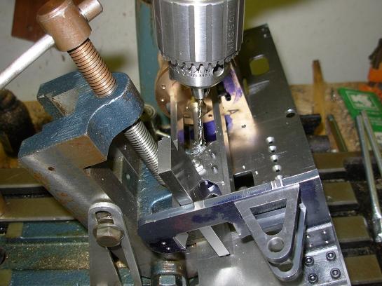
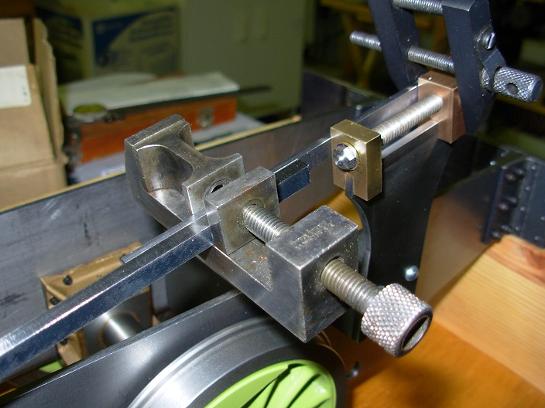
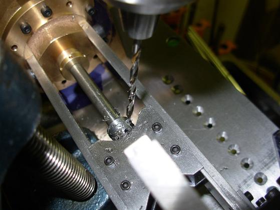
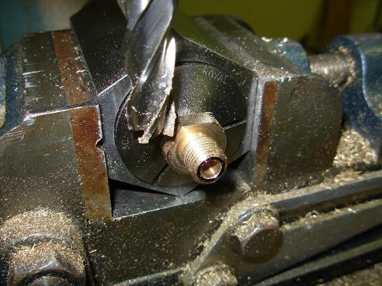
Everything in place for drilling the holes for the taper pins.
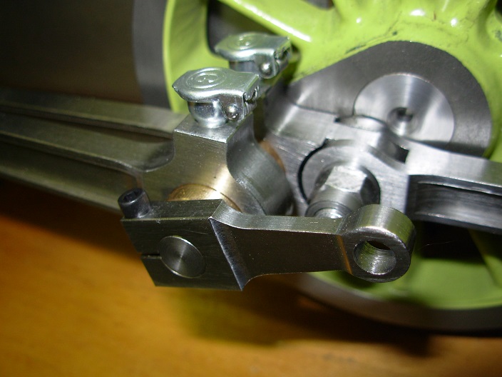
Brackets for the expansion link.
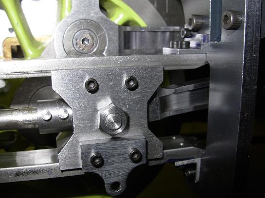
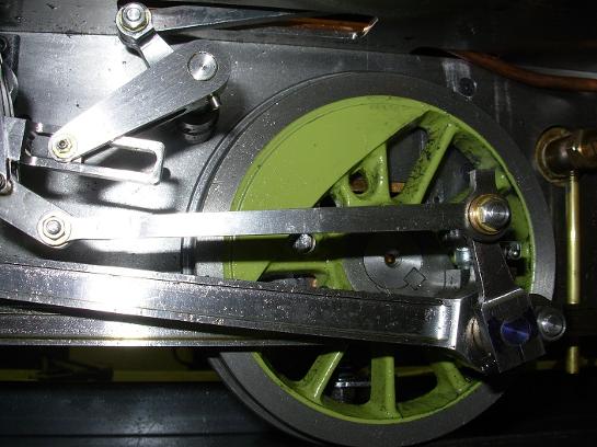
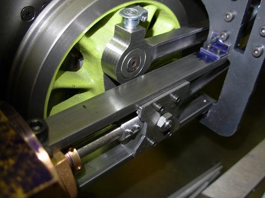
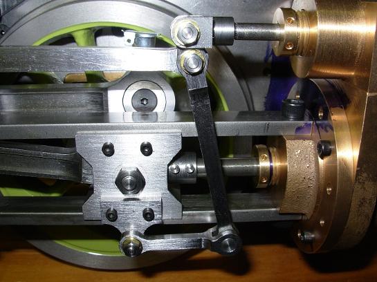
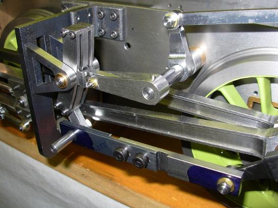
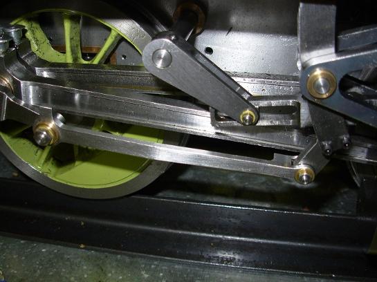
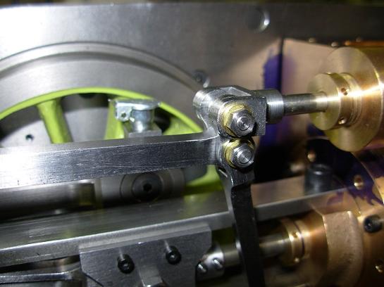
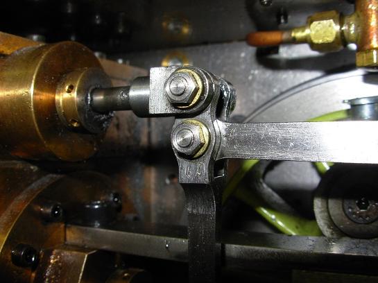
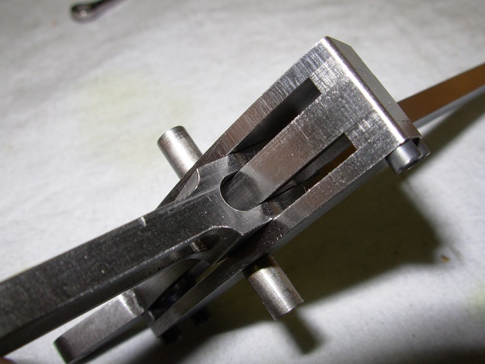
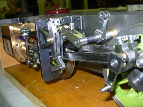
Close up view of the cross head.
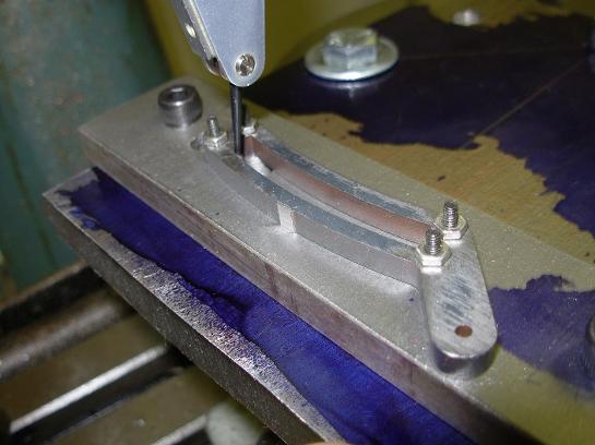
The expansion link was made from a laser cut piece of steel.
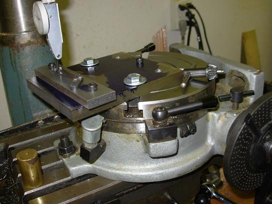
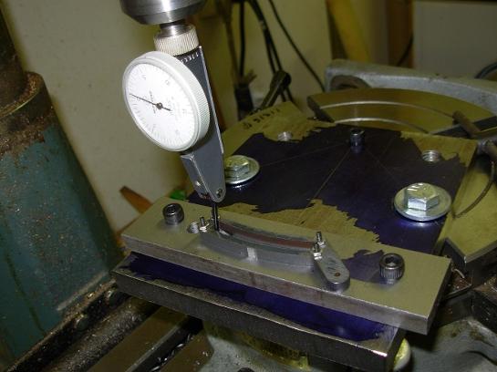
A jig was made to extend the rotary table to get the correct radius.
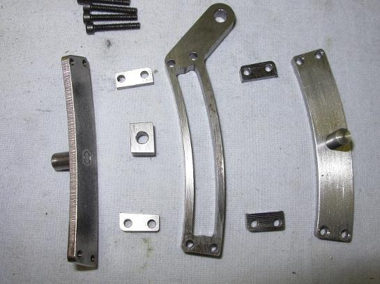
The expansion link has several parts.
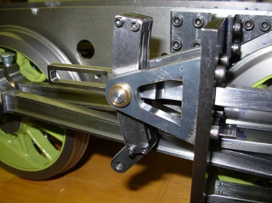
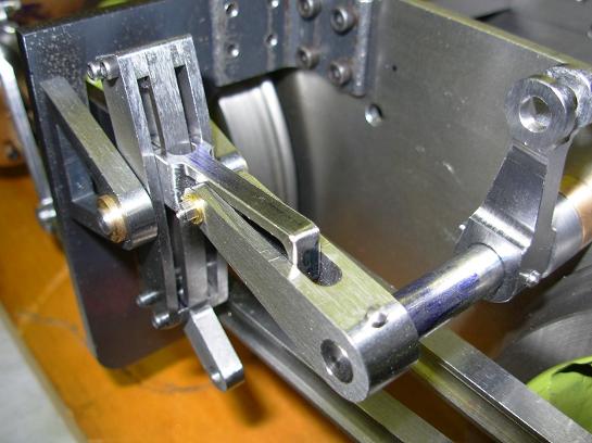
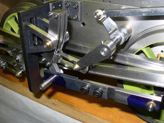
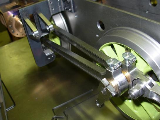
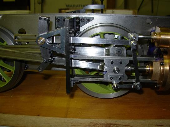
Radius rod installed through expansion link.
Lifting arm for radius rod.
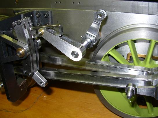
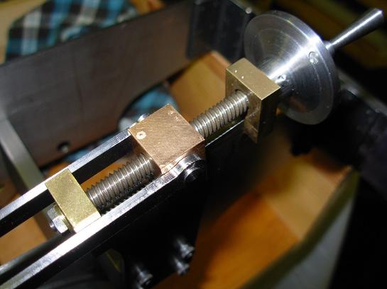
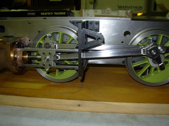
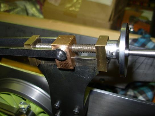
Reach rod length being set.
The screw reverser attached to the reach rod.
Temporary eccentric rod in place for valve setting.
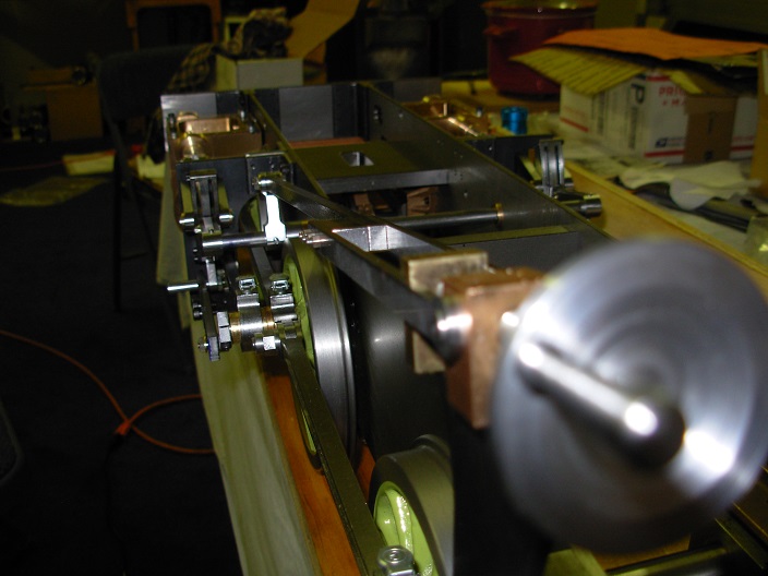
The start of setting the valves.
The start of setting the valves.
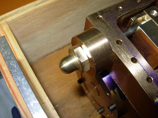
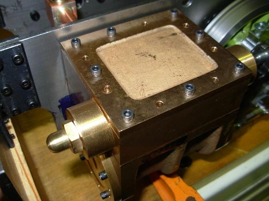
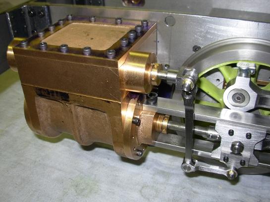
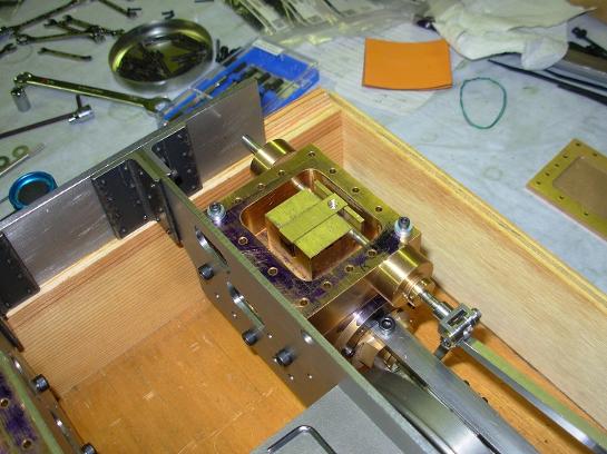
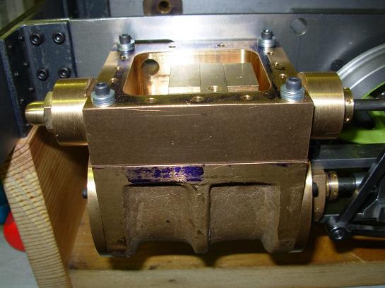
Steam chest with finished cover in place.
A finished eccentric rod in place.
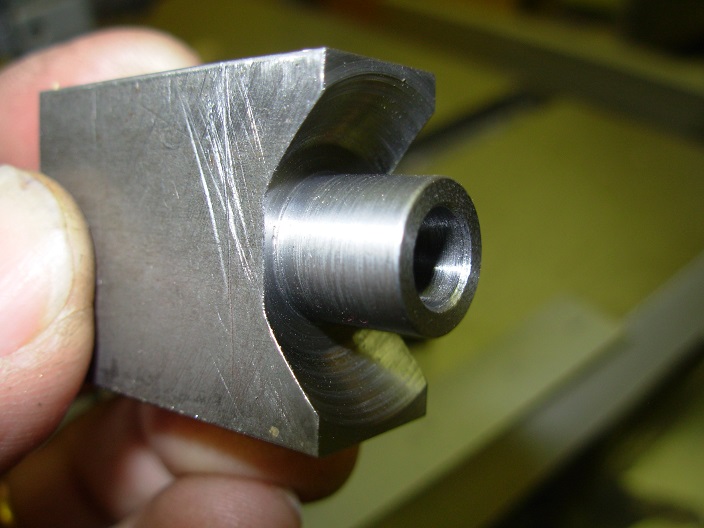
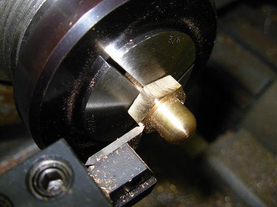
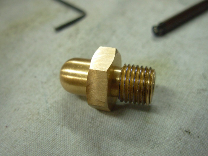
One end is turned for the piston rod.
The inside of the cross head is machined away for the connecting rod.
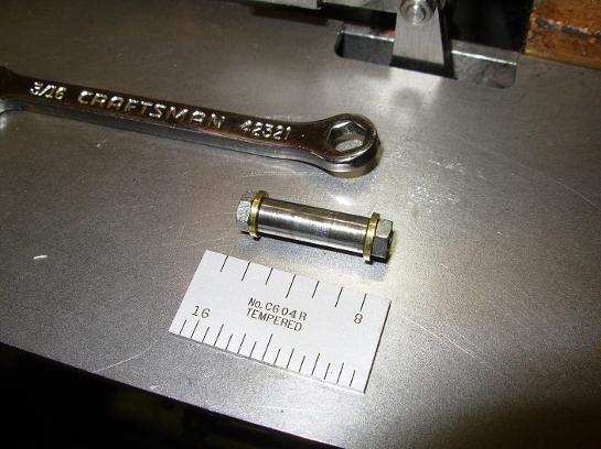
The cross head is attached to the piston rod with two taper pins.
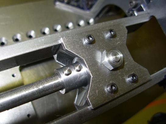
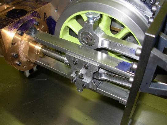
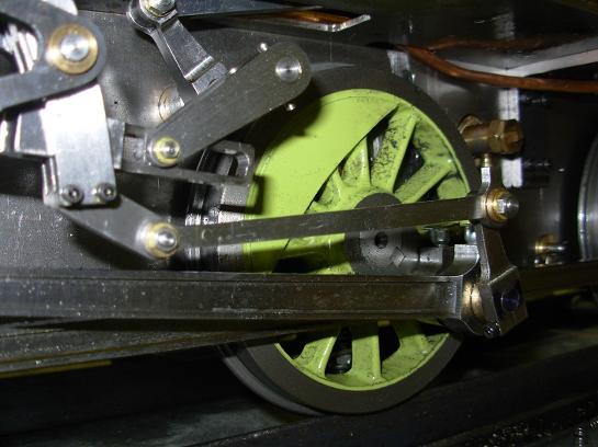
The finished cross head in place with the taper pins installed.
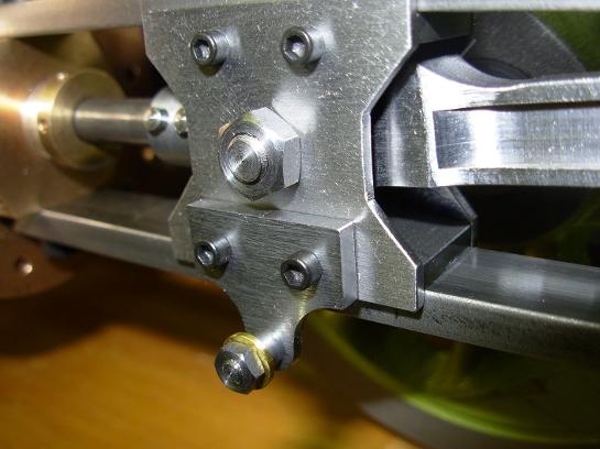
Return crank and oil cups in pace.
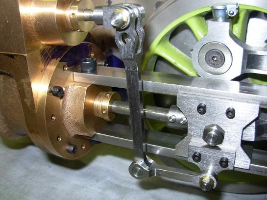
Combination rod and union link in place.
All edges needed to be machined. A job for the rotary table after the part is dialed in.
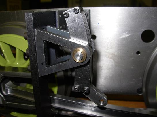
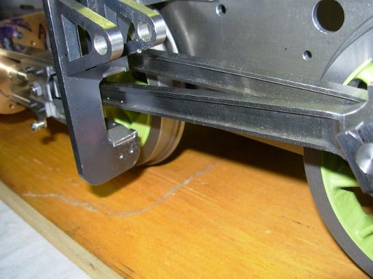
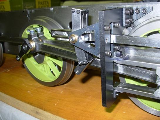
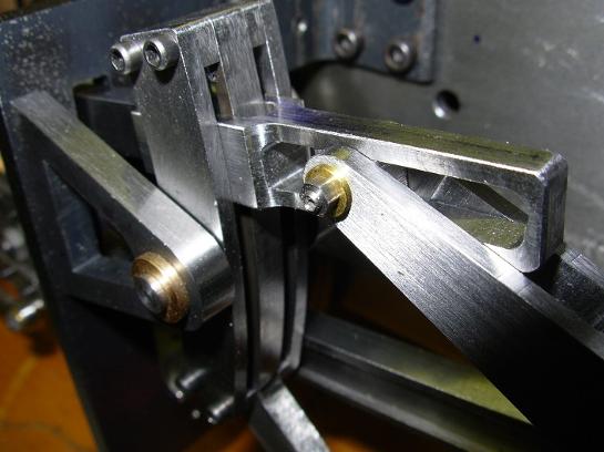
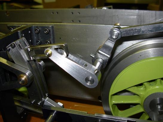
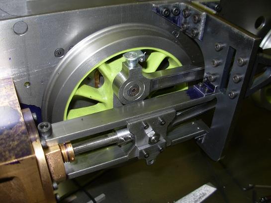
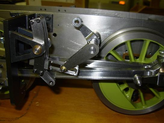
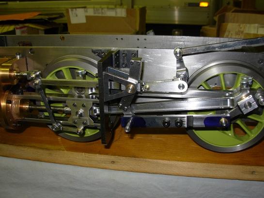
Here's the expansion link installed in it's brackets.
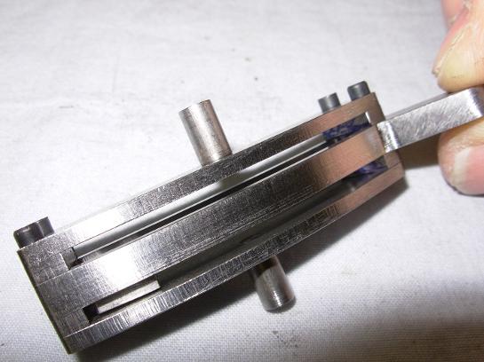
All of the parts stack together held by four screws.
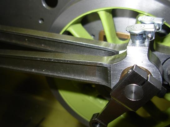
Other end of radius rod in the combination rod.
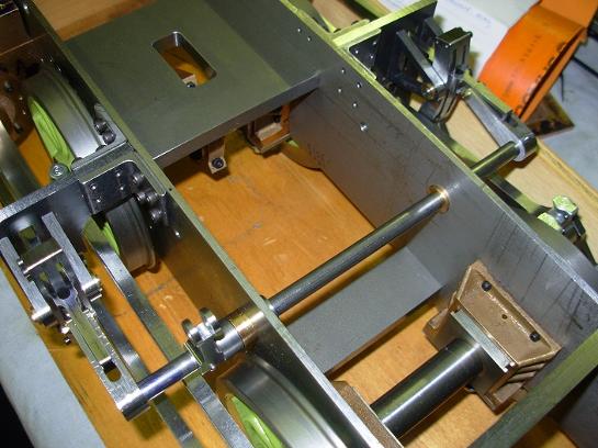
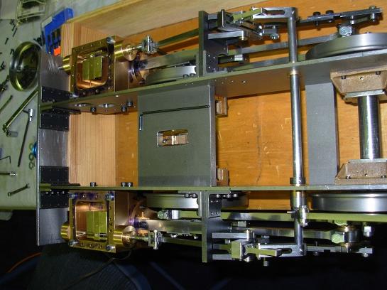
Weigh shaft and lifting arms.
Screw reverser.
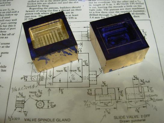
Beginnings of the slide Valve.
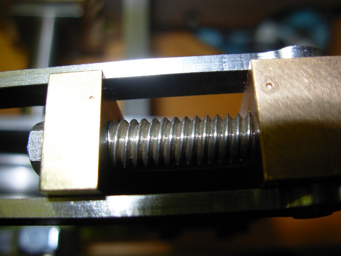
The reverser has a double lead left hand thread.
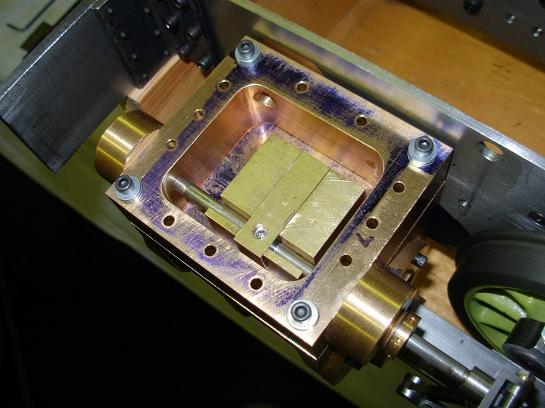
Slide valve in place.
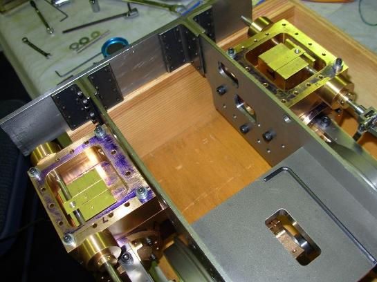
Rarely do you get to see both steam chests open at the same time in one image.
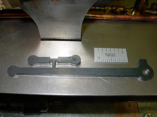
The starting pieces for the eccentric rod. These are laser cut steel.