Plates & Tubes - 2
Following, is the procedure I followed for forming and silver soldering the plates and tubes of the boiler. Also shown, is the installation of the assorted threaded bushings that will hold the many different boiler fittings. The bushings are made from a cast piece of Gunmetal, or Bronze. This material was supplied from Blackgates. Phospher bronze could also be used instead. Do not use brass for any bushing soldered into the boiler due to the presence of zinc. All of the stays and threaded fasteners for holding things together during the solder process were either bronze or copper.
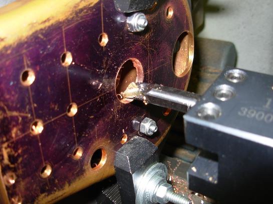
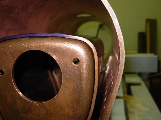
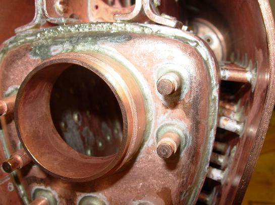
The fire hole is being bored.
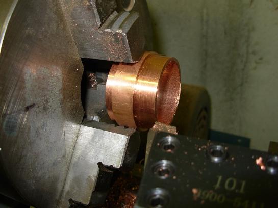
The fire hole being machined.
The foundation ring complete.
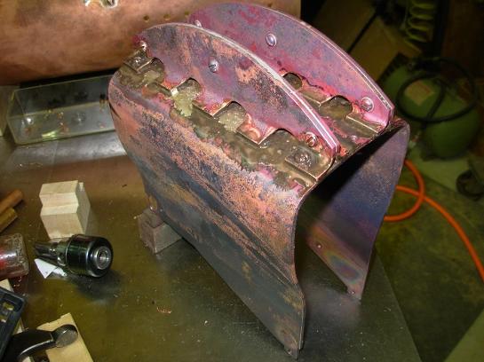
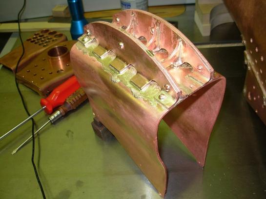
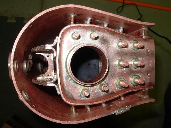
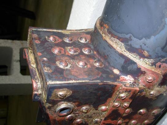
Girder stays soldered on the top of the fire box.
Here's the fire box all cleaned up.
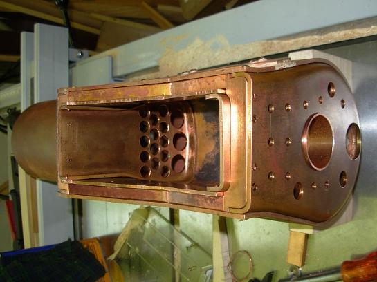
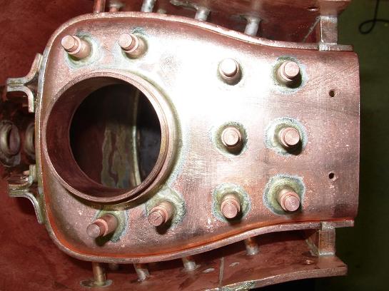
The tube sheet of the fire box silver soldered to the inner wrapper.
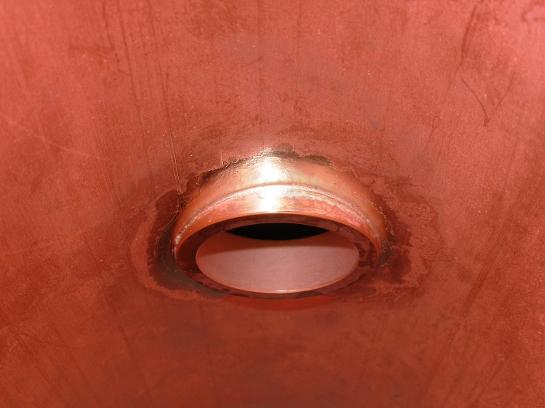
The leg extension has been attached. Also installed, is the bushing for the blow down valve.
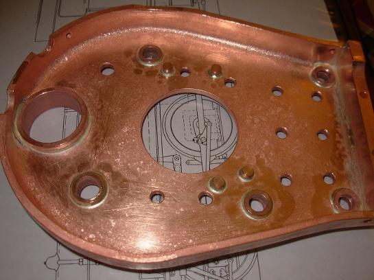
Here, the boiler has been cleaned up and readied for another heat up. The brown "dirt" around each fitting is flux to keep the joint free from oxygen while being heated.
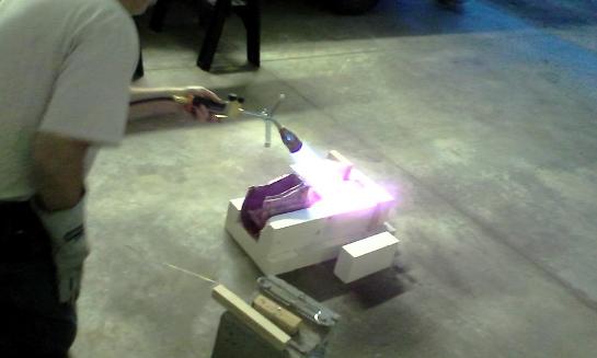
The boiler is brought up to temperature, and the silver solder rings melt and flow.
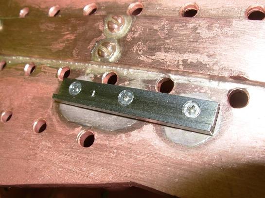
Here's one of the boiler mounting brackets test fitted to the bushings just soldered in.
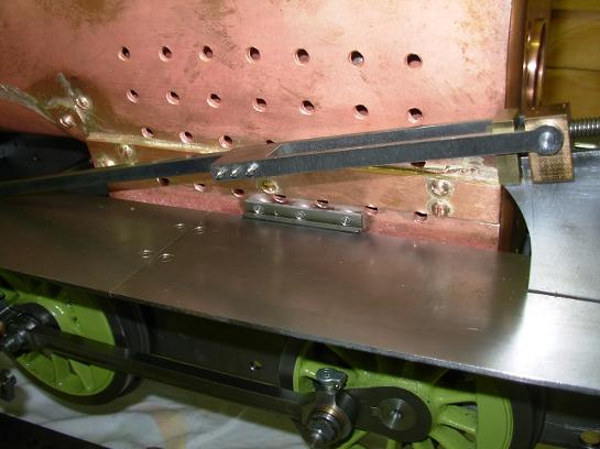
There is another bracket that sits on top of the boiler bracket. This bracket is fastened to the locomotive frames.
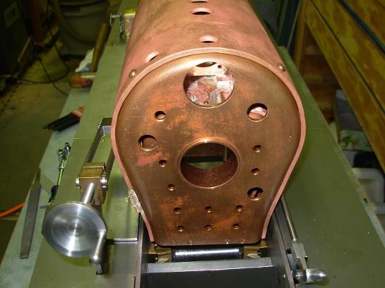
The back head fitted in place.
Another test of the boiler to the frame.
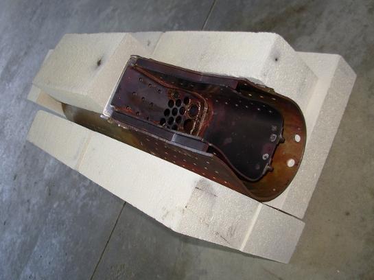
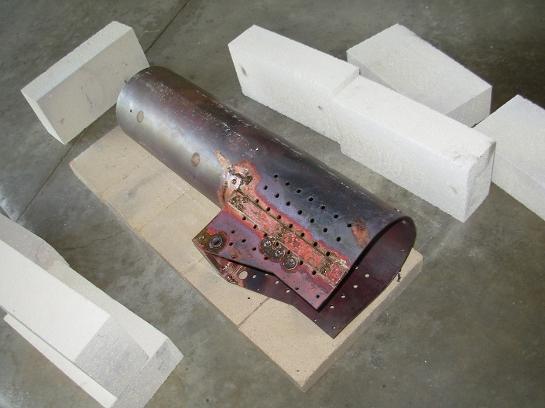
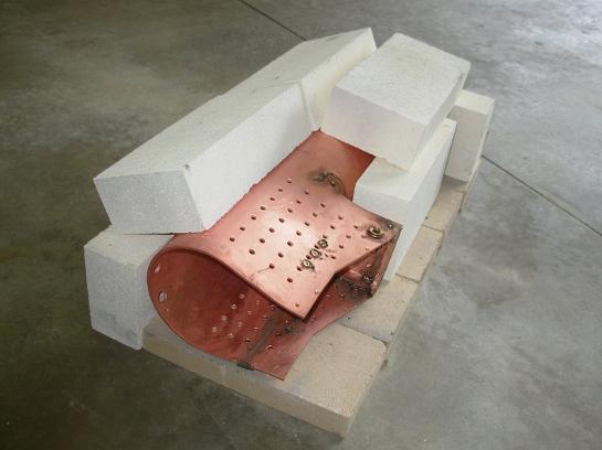
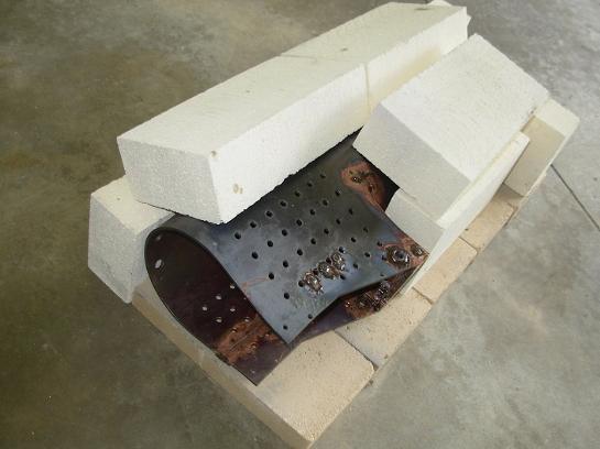
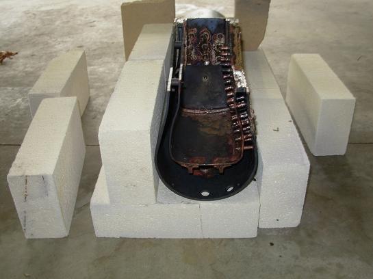
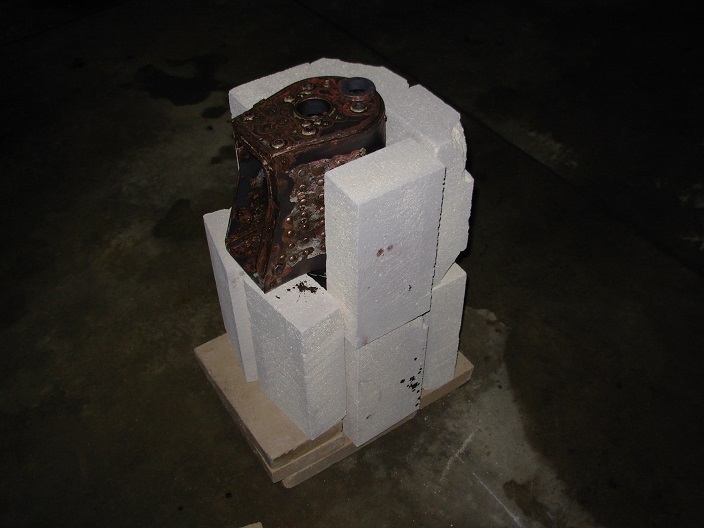
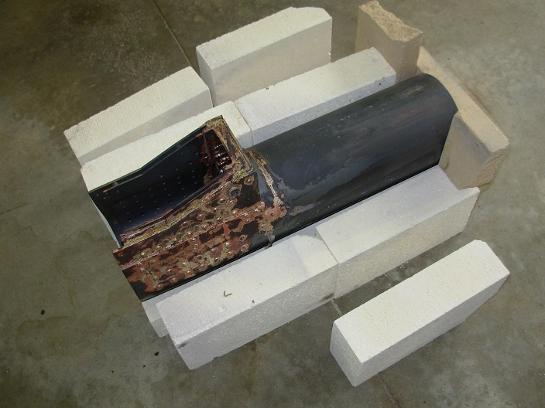
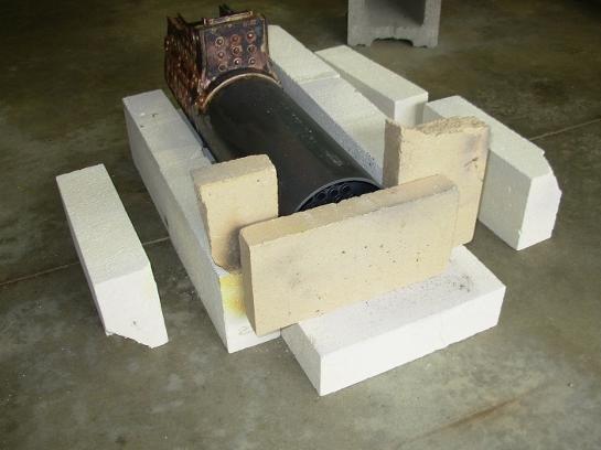
When heating up, the entire boiler becomes a heat sink. You must put heat in faster than it can radiate, so a hearth is made of heat reflective bricks.
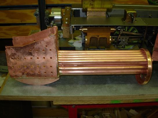
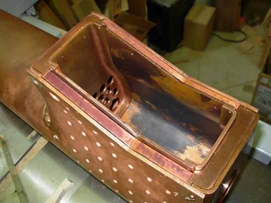
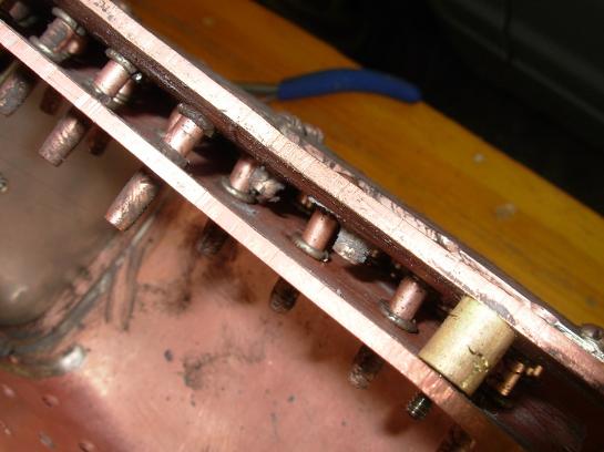
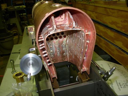
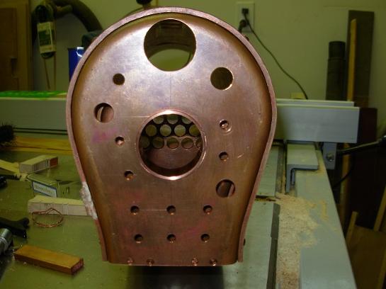
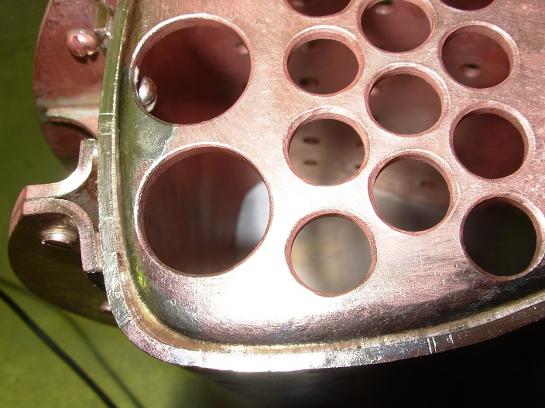
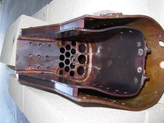
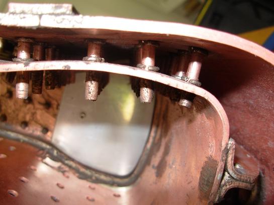
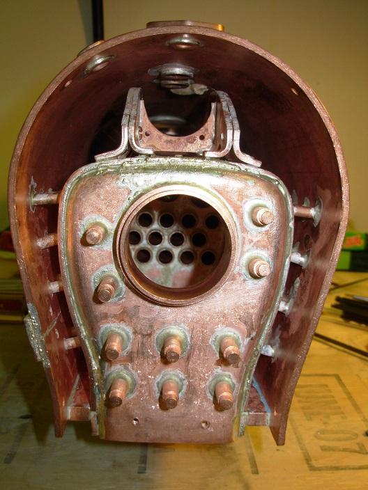
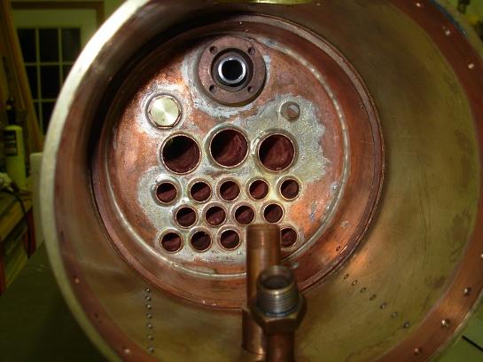
Here's the fire box with all of the tubes soldered to it.
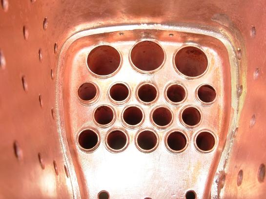
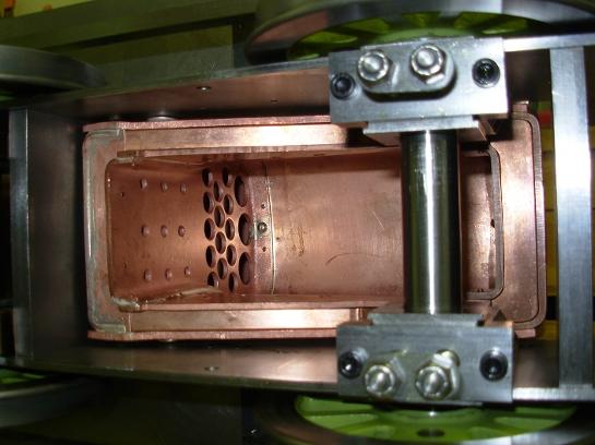
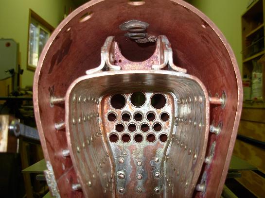
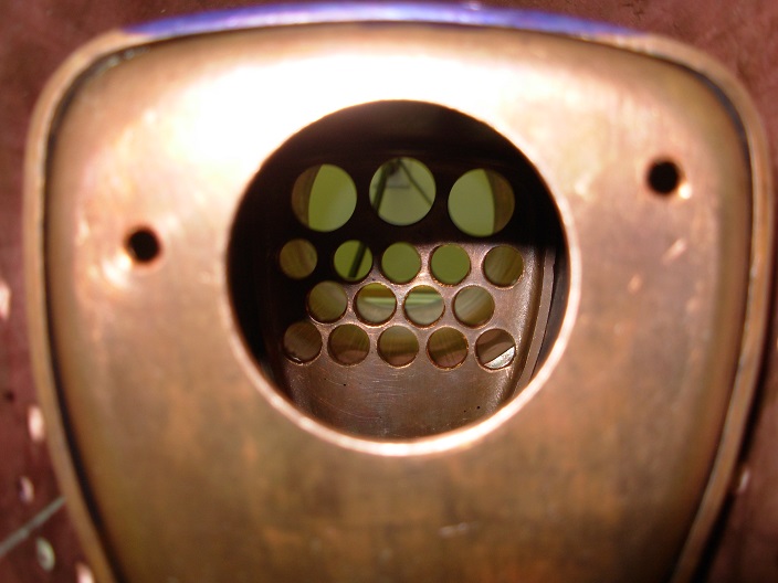
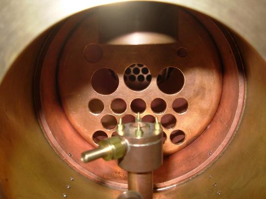
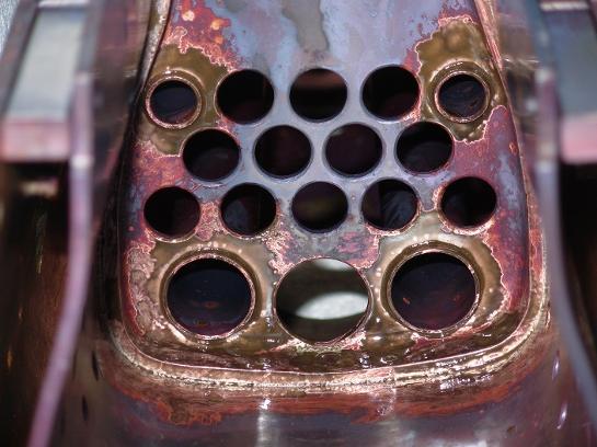
Inside the fire box looking at the fire tubes.
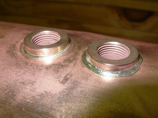
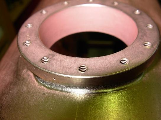
Safety valve bushings.
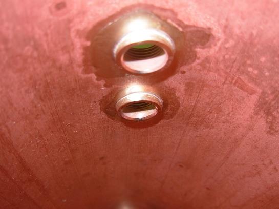
Inside of the boiler to see the safety valve bushings.
Stays for the throat plate, inside.
Getting ready to solder the stays for the fire box. Each stay has a solder ring and flux put in place.
I made a special pair of pliers to install the solder rings.
Temporary spacers were made to keep the fire box in place while soldering the stays.
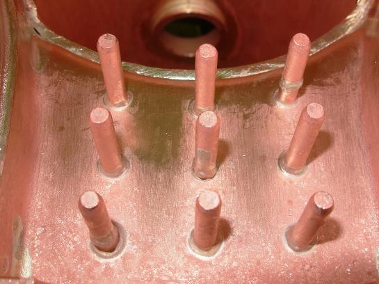
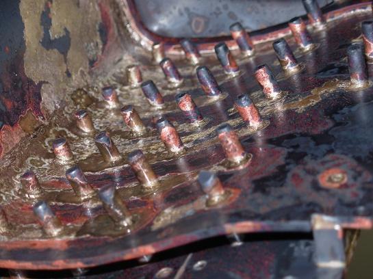
Stays inside the fire box are left long until after everything is cleaned up.
Boiler cleaned up. No fire box back, or,back head yet.
Stays all trimmed up, but, not too short.
Stays sticking out of the back of the fire box will be soldered into the back head.
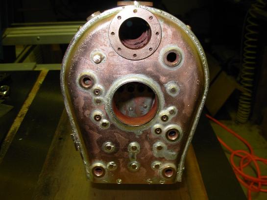
Back head with all bushings in place along with silver solder rings and flux.
Fire box back soldered in.
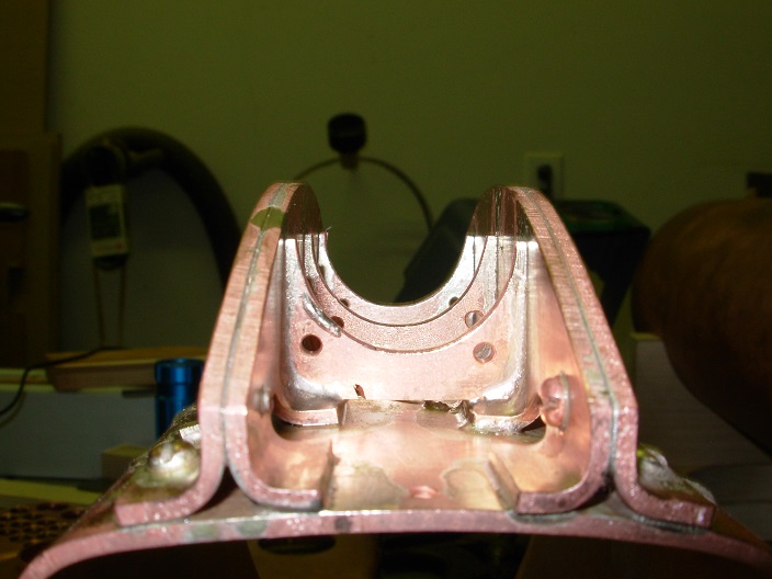
Inside the fire box after soldering.
Back head after heat up. Lots of fire bricks to keep the heat in.
The back head after clean up. This boiler passed its hydro test in May of 2017 at the Finger Lakes Live Steamers club.
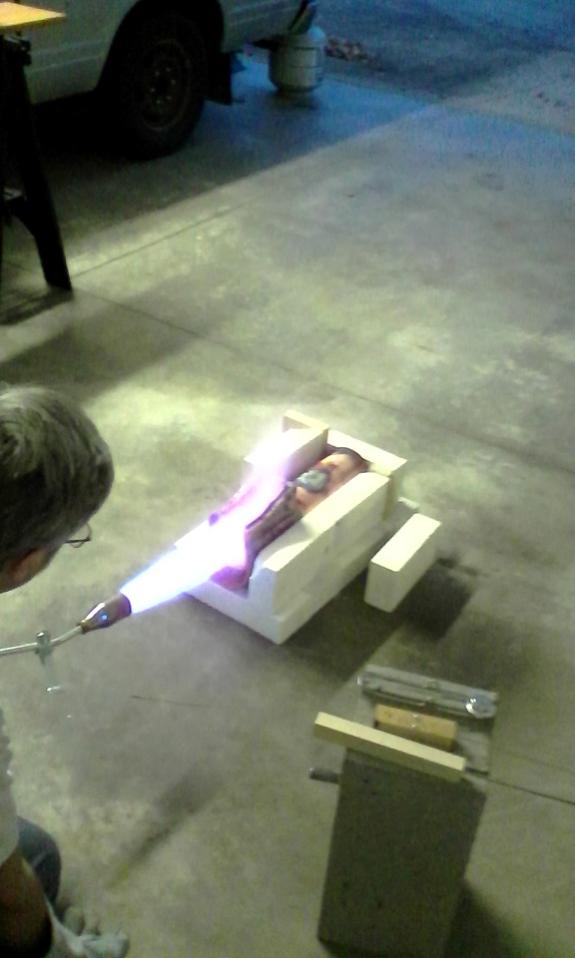
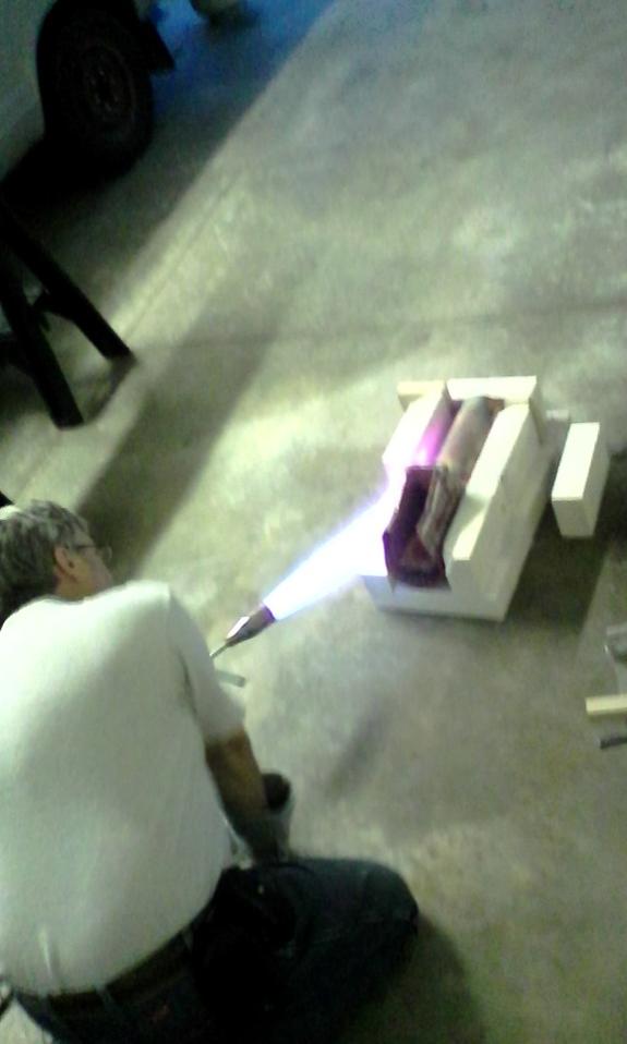
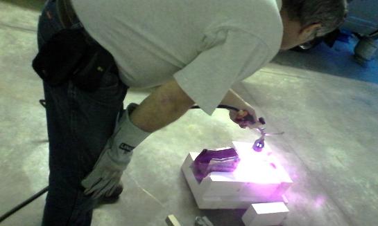
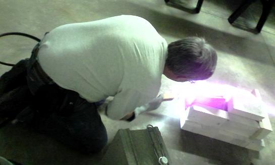
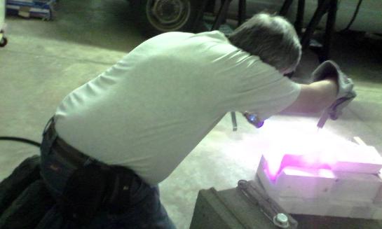
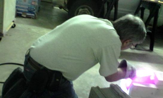
My wife took a few photos while I was doing a heat up.
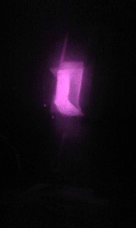
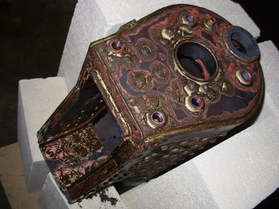
Immediately after a heat up, I took a photo with the lights turned off. The camera showed the boiler as purple, the actual color was dull red.
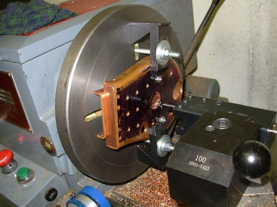
The fire hole is bored together with the inner back plate of the fire box. This assures alignment.
The fire hole test fitted.
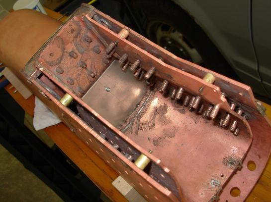
All major components ready for silver soldering.
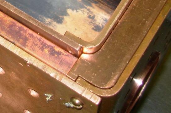
A close up of a corner of the foundation ring.
Things look pretty dirty before cleaning in acid.
The cut out between the girder stays is for the throttle tube that runs fore and aft inside the boiler.
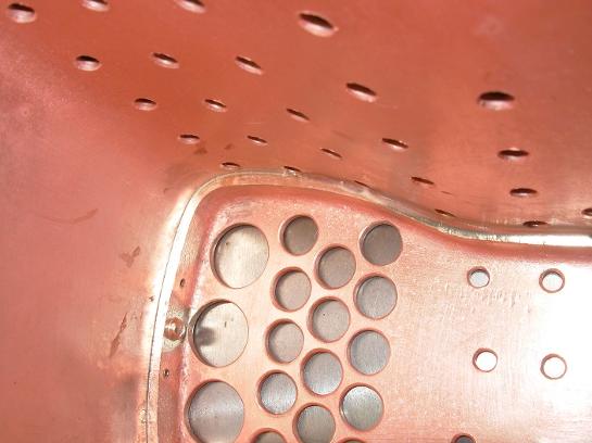
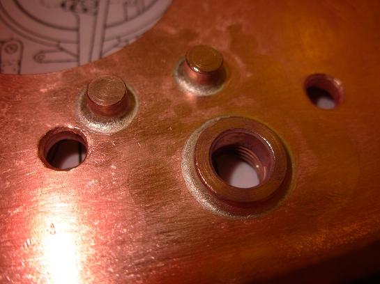
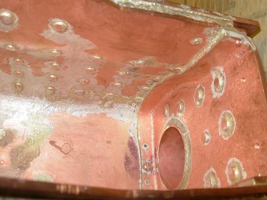
Good penetration of the silver solder.
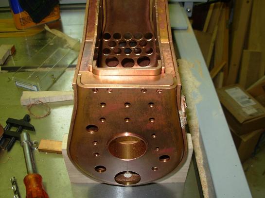
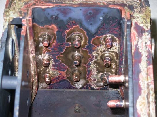
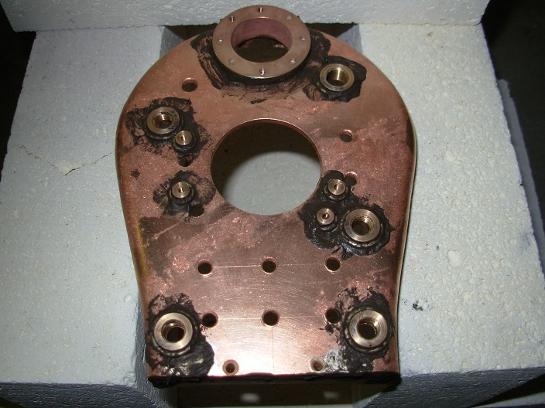
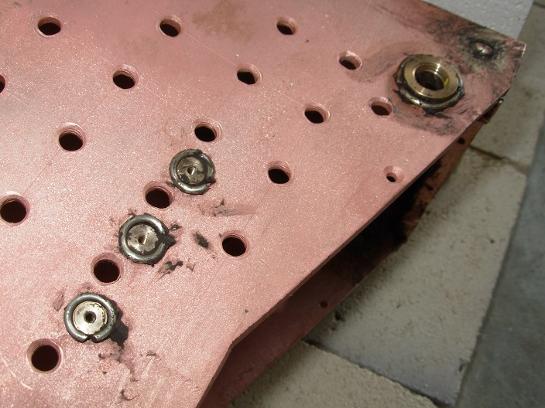
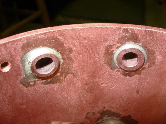
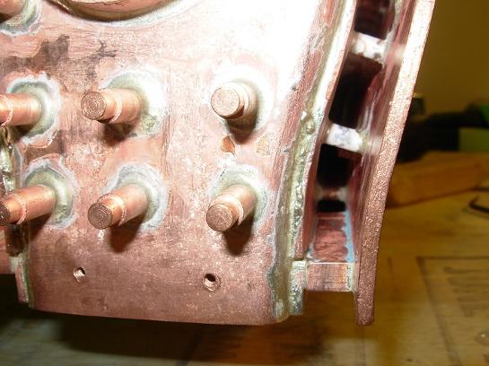
Three blind threaded bushings are installed for the boiler mounting brackets.
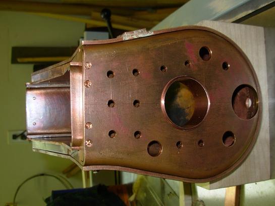
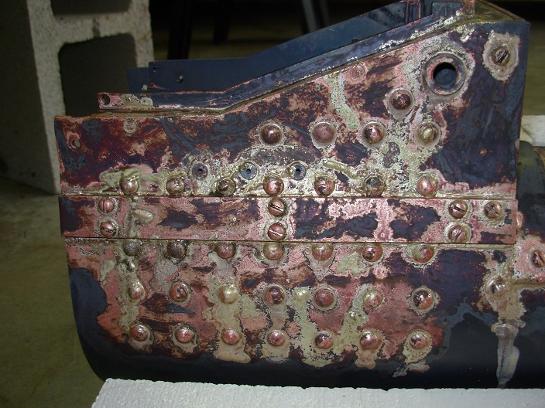
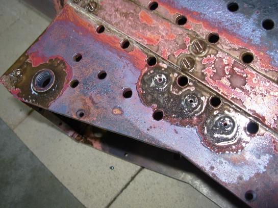
This time, the mounting brackets are installed on the other side along with the blow down bushing. A ring of silver solder is place around each fitting along with a bit of flux.
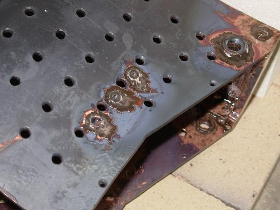
Things look pretty messy after the heat up, but, actually the silver solder has flowed quite well.
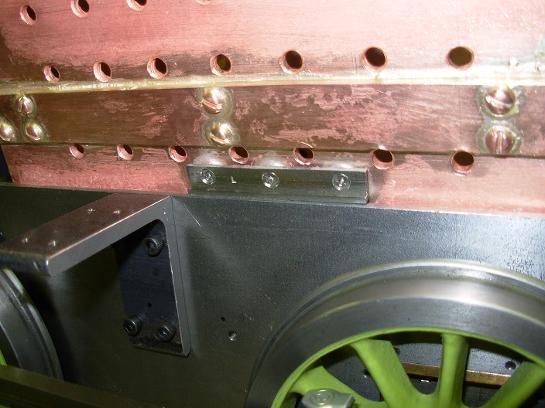
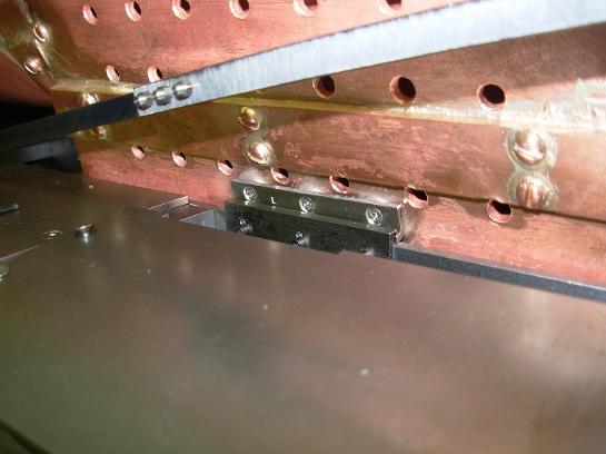
The boiler mounting brackets sit on the top edge of the locomotive frames.
This creates a joint that can slide along the top of the frame as the boiler gets a little longer when it heats up, yet, the boiler is locked to the frame.
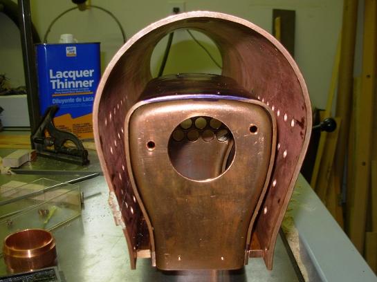
Looking into the smoke box.
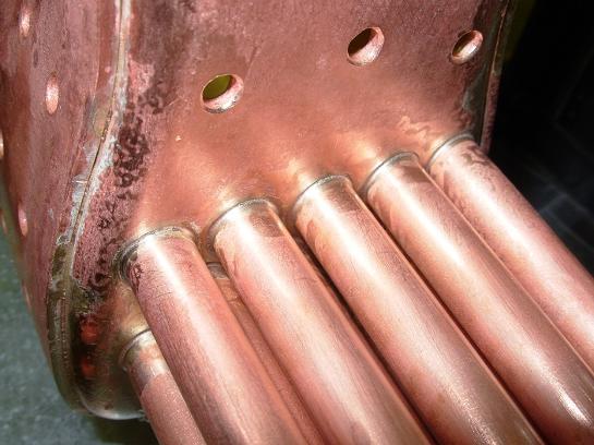
A few of the fire tube have been soldered in.
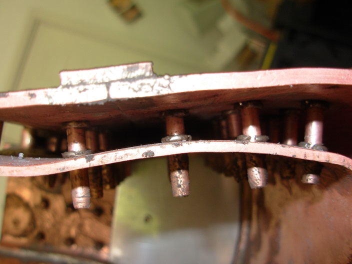
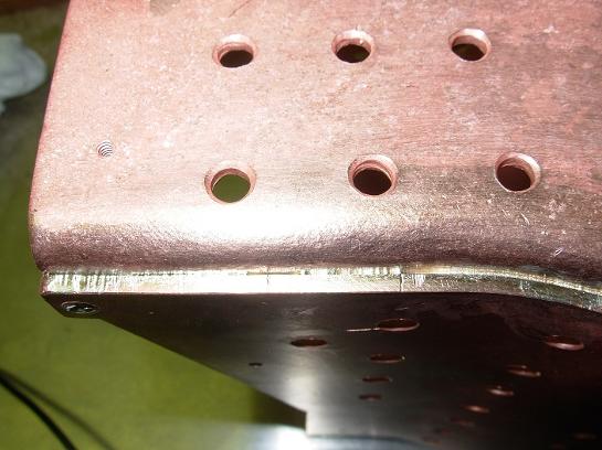
The first four tubes are soldered in place just to see how things would go. They turned out well enough that I soldered up the rest, all at the same time.
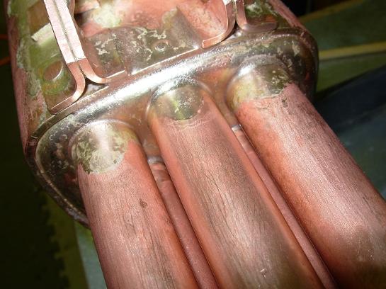
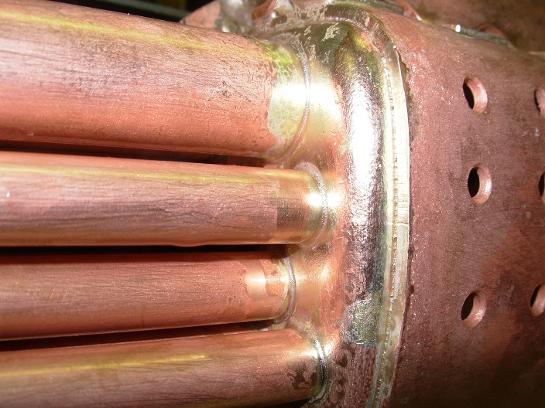
A close up of the fire tube joints. They all turned out quite well.
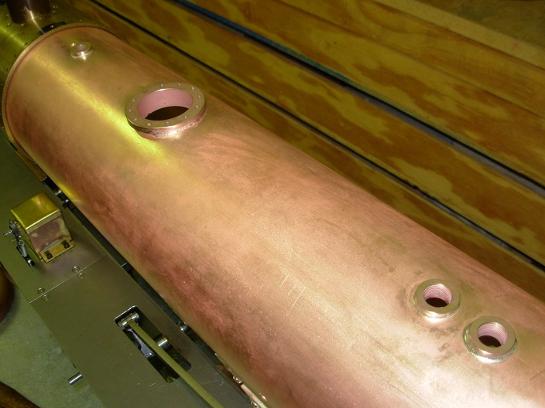
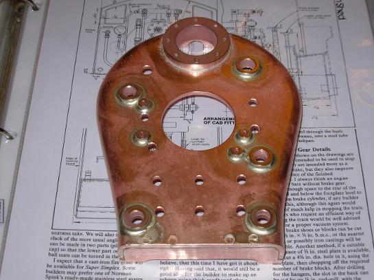
The bushings on the top of the boiler in place.
The bushing for the steam dome.
This is inside the boiler to see the steam dome bushing.
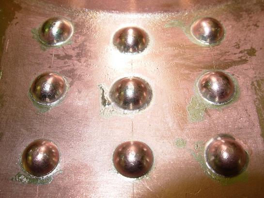
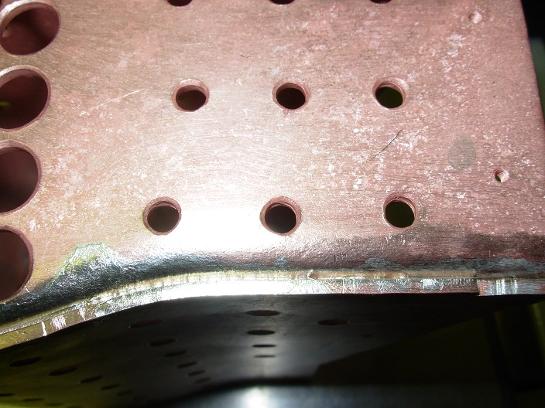
Stays for the throat plate, outside.
The preparation for the fire box stays took about 3 hours for one side.
Plenty of flux is applied to the outside of the fire box. Flux is also applied to previously made joints to protect them from the heat.
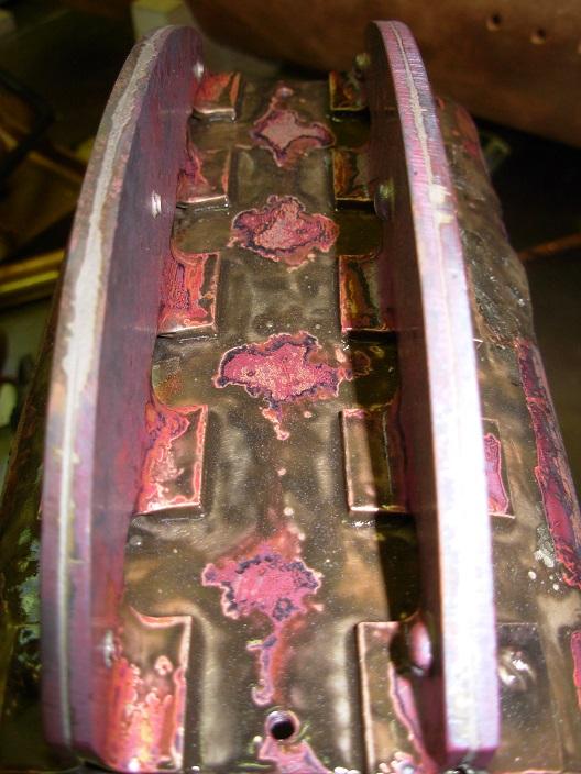
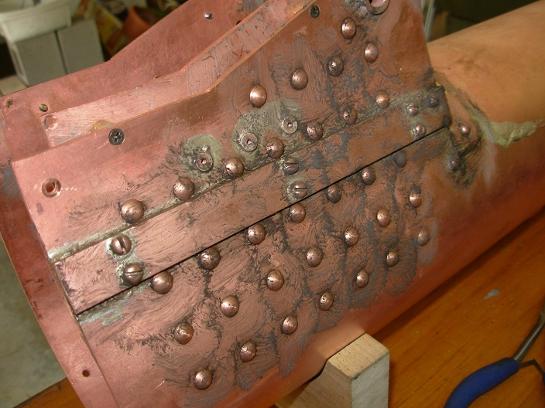
After the heat up, things are pretty black.
Solder has flowed every where, including where it should!
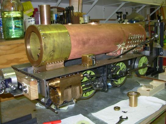
Another test fit, mostly to see how things look while in the locomotive frame.
Back of the fire box being fitted.
Bushings installed into the boiler top for the water gauge and steam turret.
The back head after the heat up and clean up. Good flow on all joints.
Foundation ring soldered in.
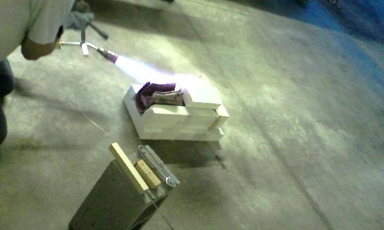
Only the part being heated is exposed from the hearth.
The smoke box tube sheet is heated up and soldered last.