Water Tanks & Plate Work
Following, is the construction of the water tanks, piping and other plate work. As mentioned in the section on the injector, the entire water system and piping was actually done twice. First, as a temporary system before the final water tanks were built. Then, as a final system for connection to the finished water tanks, axle pump, injector, and emergency pump.

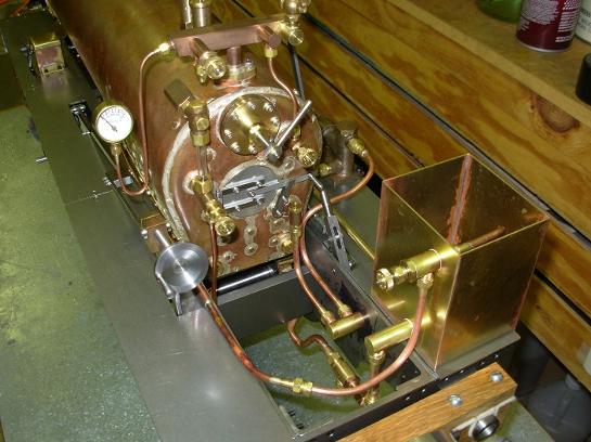
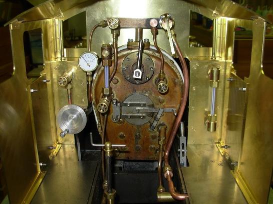
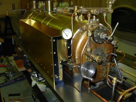
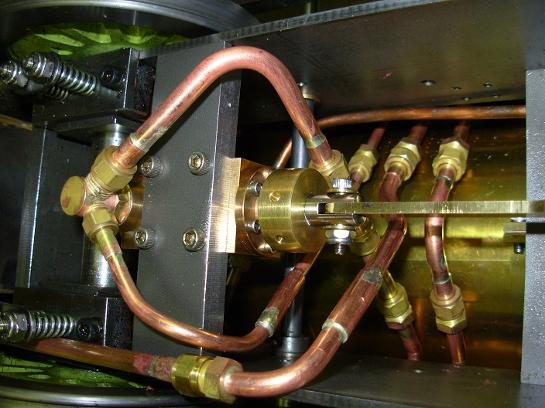
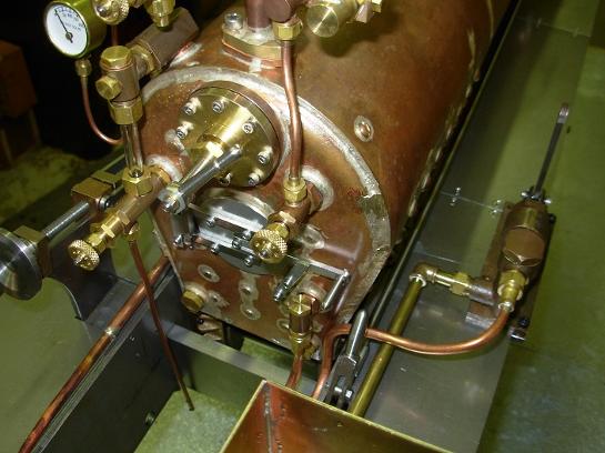
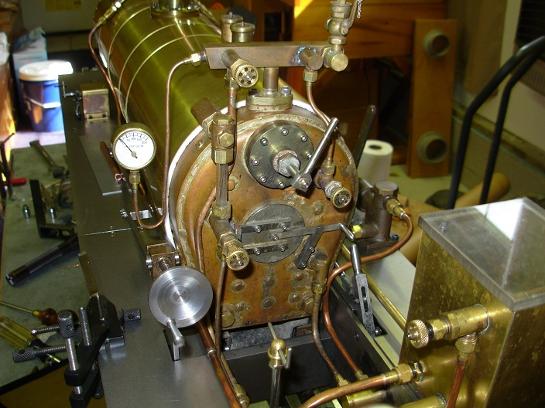
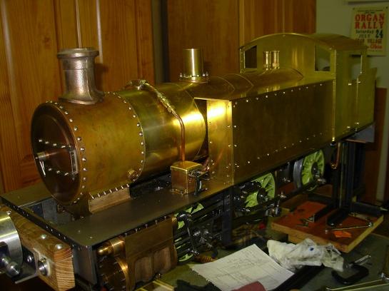
Here's an overall view of the first water and piping system. Visible on the right hand running board is the temporary dump tank and hand pump.
The hand pump gets it's supply from the dump tank.
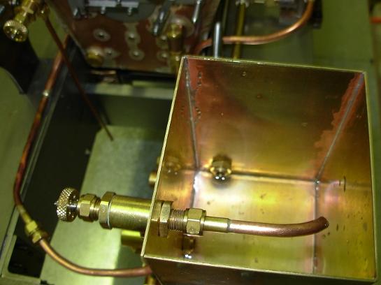
This is a good view of the by pass valve and the discharge pipe into the dump tank.
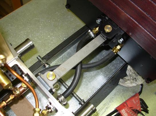
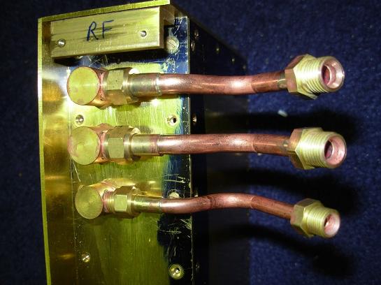
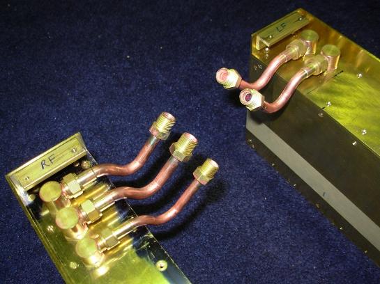
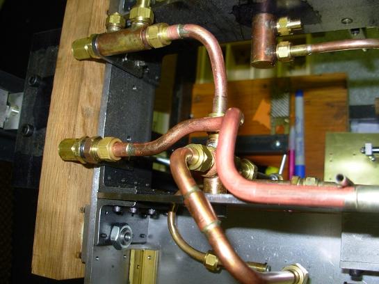
There are two water supply lines coming from the tender/riding car. The lines criss cross so there is less stress on the lines when going around a curve.
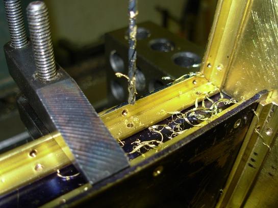
All of the plates of the water tanks are fastened to each other by 1/4" brass angle.
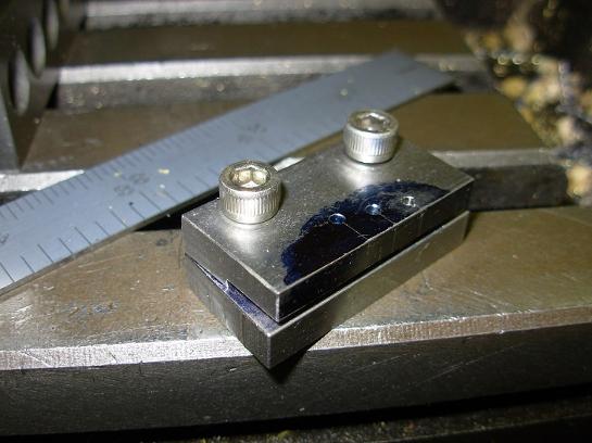
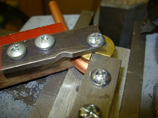
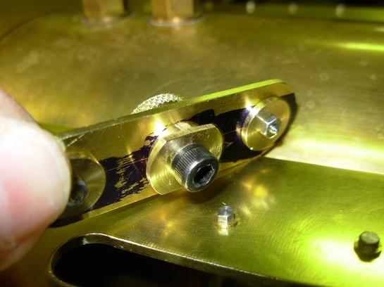
Here's a little jig I made for positioning the screw all the same distance from the edge of a plate.
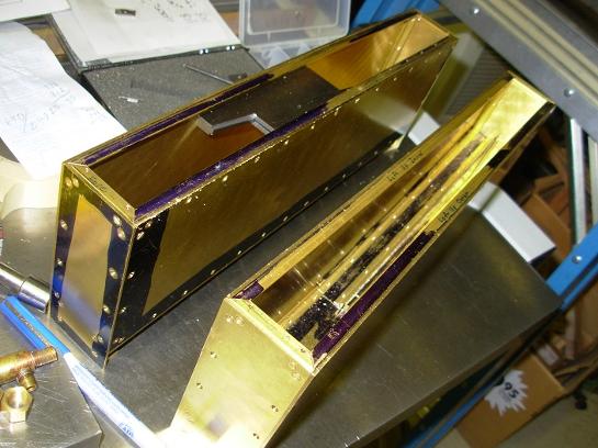
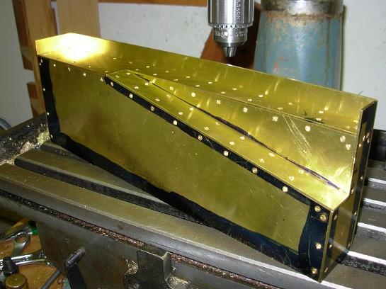
This is the bottom side of the tank that goes on the left side running board. The cut away is for clearance over the reversing gear reach rod.
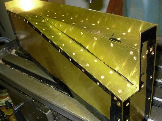
Here's the left side tank mostly complete.
The angles that will hold the tank tops, have been installed.
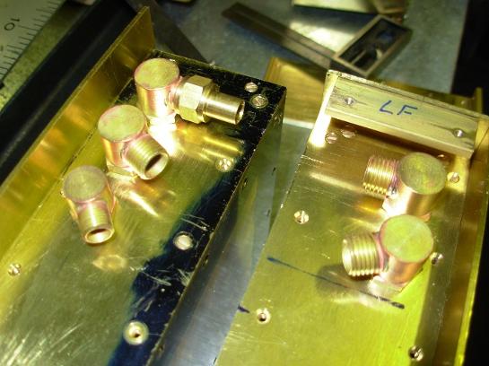
Here's the connectors on the bottom of the water tanks in position.
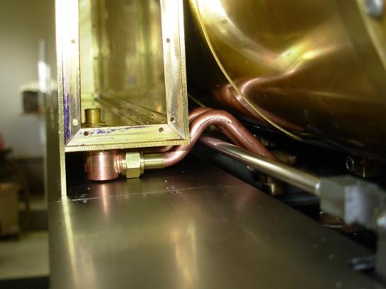
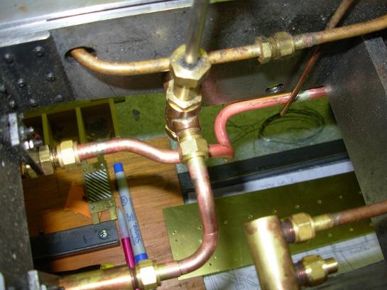
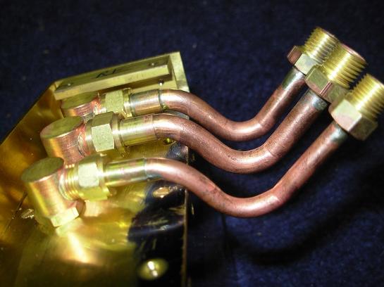
This shows why I needed some tight bends in the water pipes. Clearance was needed to get over a reach rod and then under the boiler. The water tanks were made to allow space for the bottom connectors and pipes.
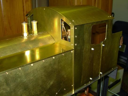
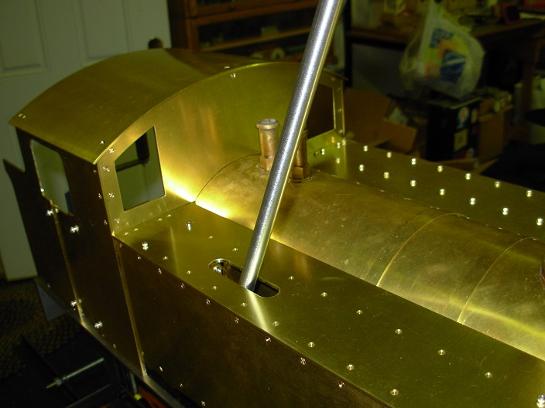
This photo shows the emergency hand pump handle in position.
The
This is a view from the bottom. The tanks are cross piped to allow for easy access with wrenches. It takes two wrenches to tighten these fittings, you must allow room for the wrenches.
Here are the two supplies entering the locomotive from the left. The upper one supplies the tanks and the lower one supplies the injector.
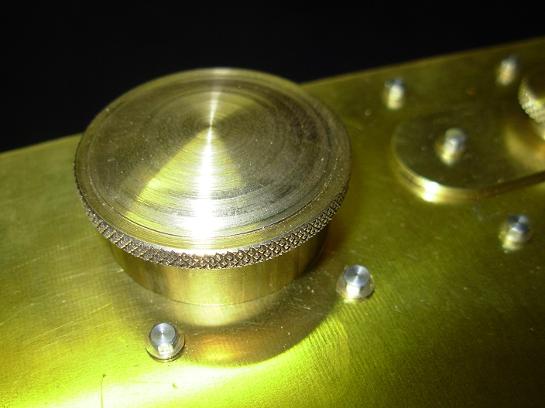
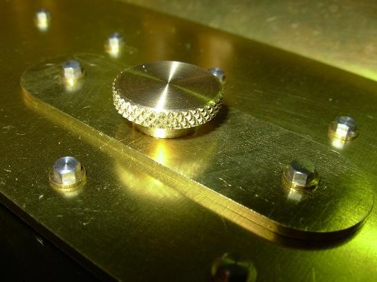
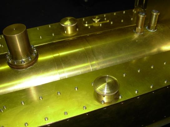
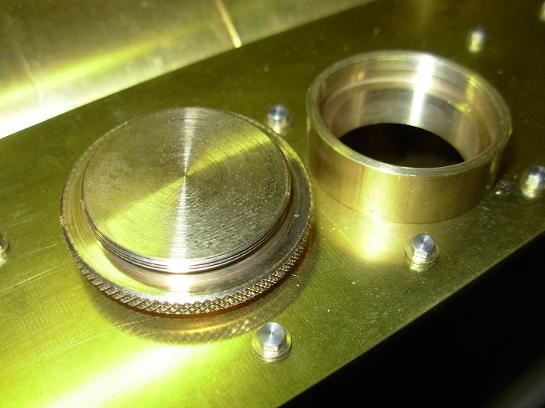
The covers are just a simple screw top.
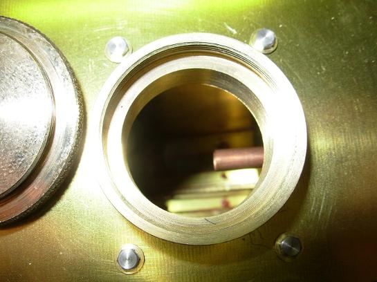
Here you can see the discharge pipe of the by pass valve through the water tank access.
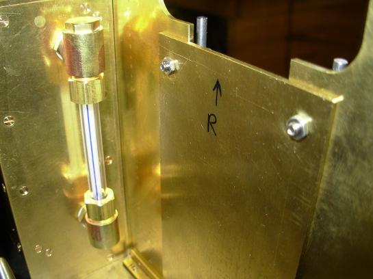
A close up view of the water tank gauge glass and the inside of the door.
On the left is a schematic of the general layout of the piping on my Super Simplex. This is something I came up with, as the drawings showed nothing about how to pipe up this locomotive. The hand pump discharge is piped so it can be used to "prime" the axle pump. This was suggested by a friend and works quite well. Below is a button if you would like to down load a copy of this.
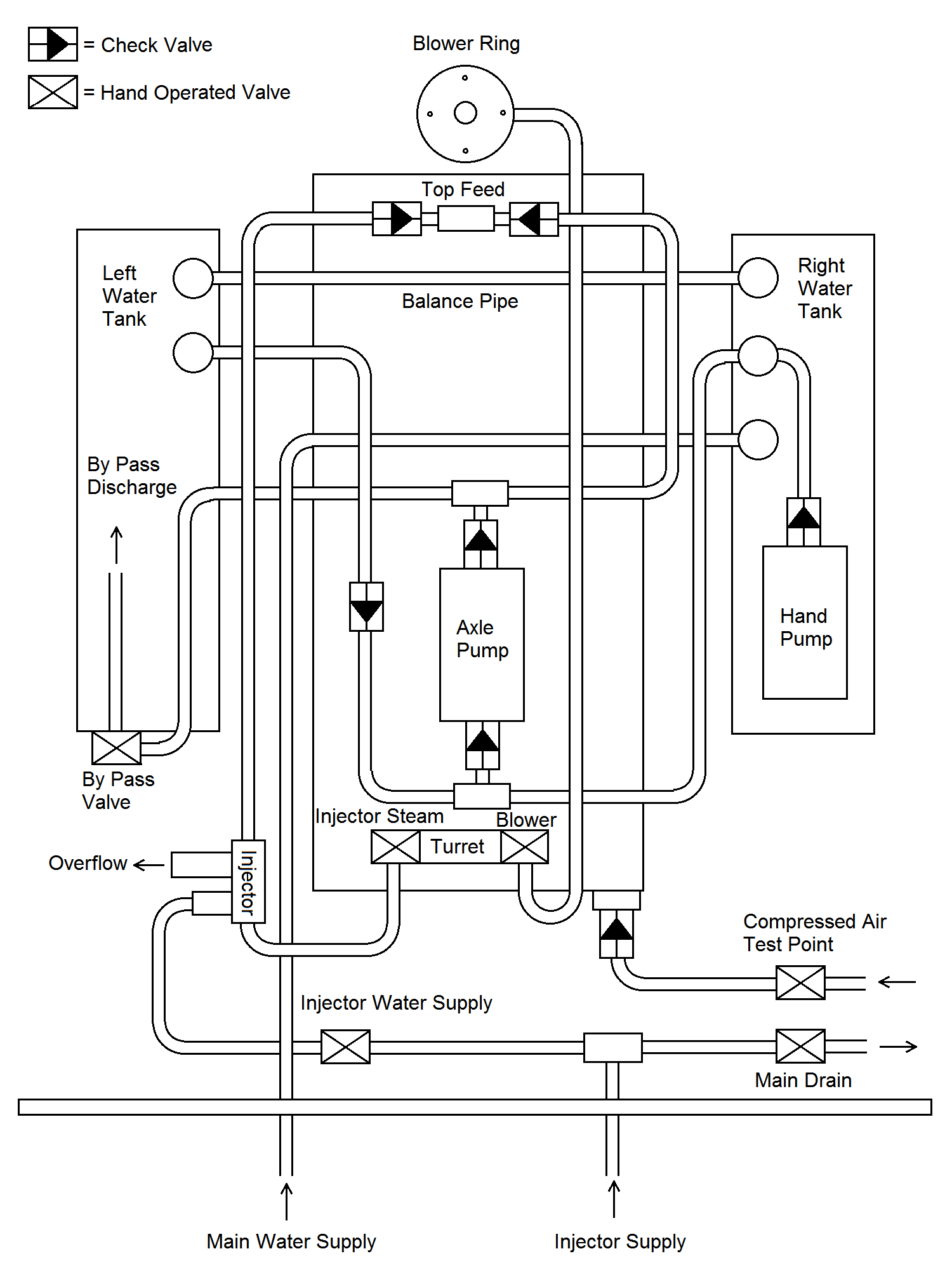
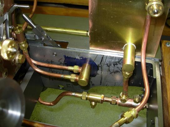
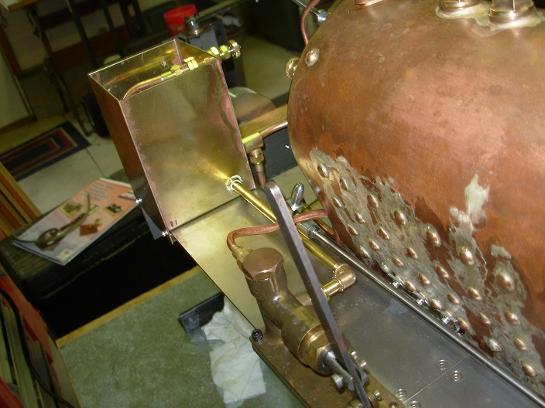
The axle by pass valve is mounted directly on the side of the dump tank.
The discharge from the hand pump is piped into the back head through a check valve.
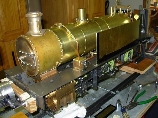
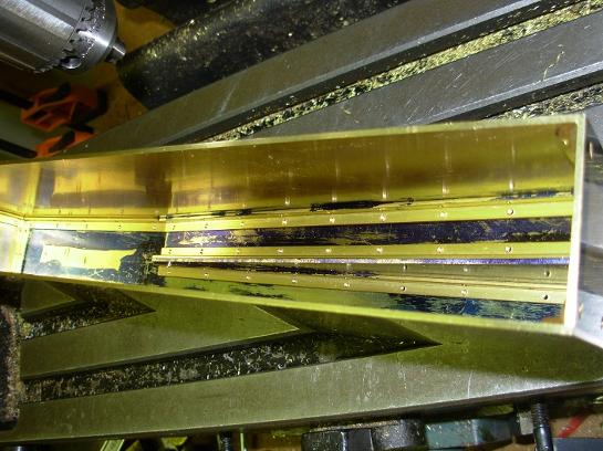
Here is one of the water tank sides temporarily positioned to observe the fit.
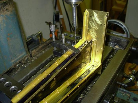
The water tanks used most of 20 feet of 1/4" brass angle.
There are many screws to hold the water tanks together. These are 2-56 flat head machine screws.
The cut away in the right hand tank made for a rather complicated assembly. But, not impossible.
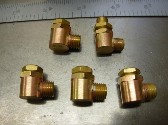
These are the connectors that will go onto the bottom of the water tanks.
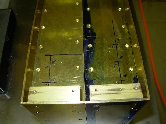
The positions for the connectors on the bottom of the tanks have been marked out.
The water lines required some very tight bends. I made a special jig for making these bends.
To assist in bending the tubes without crushing or tearing them, the tubes were filled with "Cerro Bend". After bending, the Cerro Bend was melted out. Much experimenting was done to perfect this process.
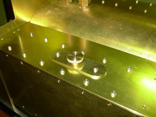
This is the cover for the hand pump handle in position. Also visible, are the hex head screws for the tank tops.
The hand pump cover is removable with a 1/4 turn.
These are the two supplies that go back to the tender/riding car. One supply is for the water tanks and the other is a dedicated supply for the injector.
Here the tank access covers have been added. The one on the left tank is to witness the discharge of the by pass valve.
"Scale" covers would be a hinged type.