Emergency Hand Pump
Following, is the construction of the emergency hand operated feed water pump. The discharge of the hand pump goes to the supply of the axle pump instead of directly into the boiler. This allows the hand pump to be able to prime the axle pump as well as to feed the boiler. A check valve must be added to the axle pump supply so the hand pump does not pump water back into the axle pump supply, but, goes through the axle pump.
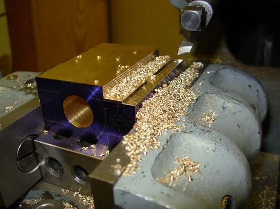
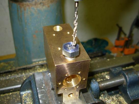
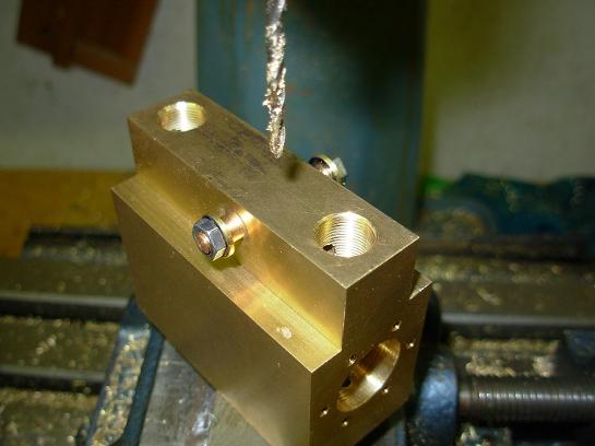
The pump body is made from a solid block of brass. Here it is being machined on the shaper.
The pump is mounted on a plate with screws that can be accessed from the top of the water tank.
With the pump installed, it was possible to position the pump handle slot.
Here are the four holes drilled using the jig.
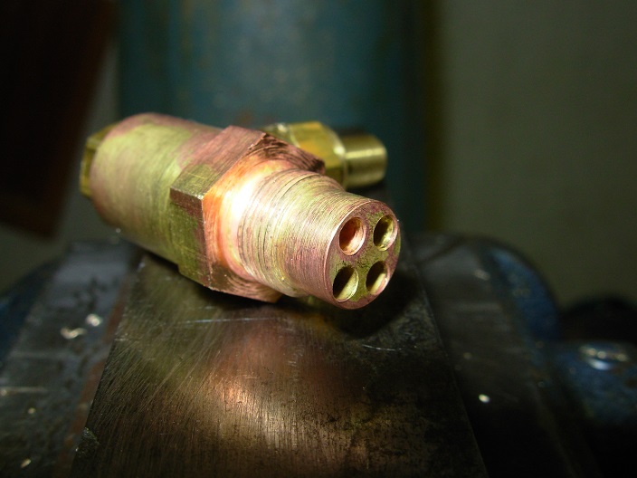
The drill jig was made in both a male and female version so this pattern could be drilled in the end of one of the connectors.
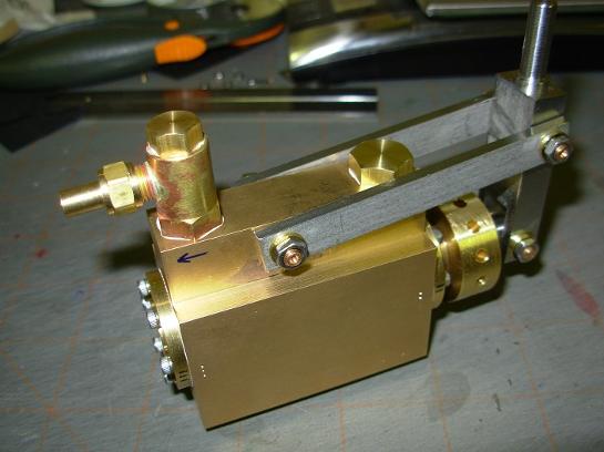
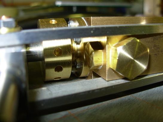
The discharge of the pump was moved to the other end of the pump from the drawing.
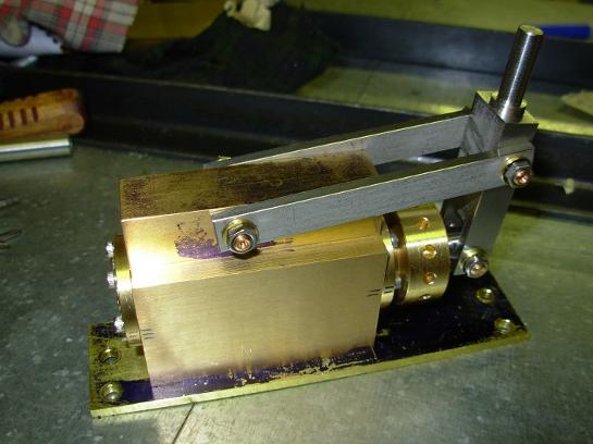
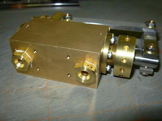
Top view of the pump.
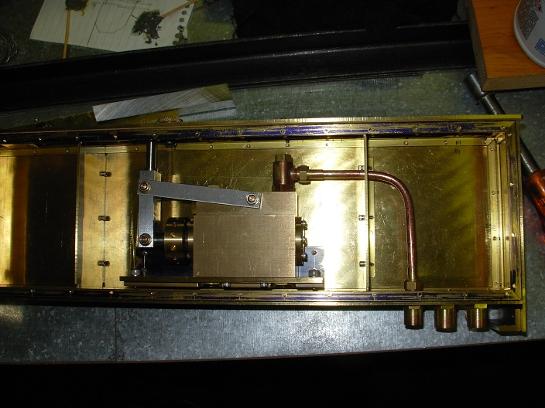
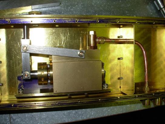
Side view of the water tank with the hand pump and discharge pipe installed. The pump is mounted to a piece of brass angle mounted to the side of the tank.
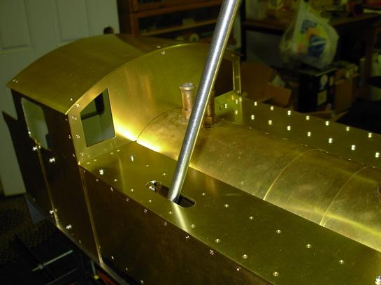
The pump handle was fitted first for a way to show exactly where the handle slot would go in the watertank top.
The hand pump mounted in the water tank. Also fitted, are the water tank baffles.
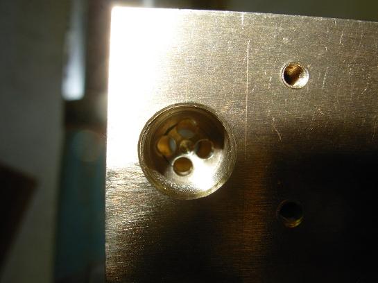
Some of the pump check valves required four small holes to be drilled in some of the ball cavities. I made a jig to drill these holes. The jig was also used for the axle pump.
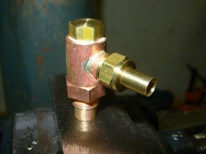
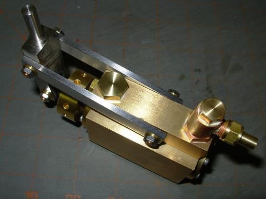
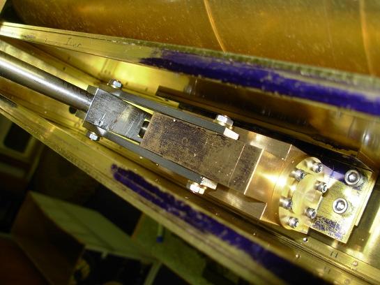
This is the discharge connector positioned on the top of the hand pump.
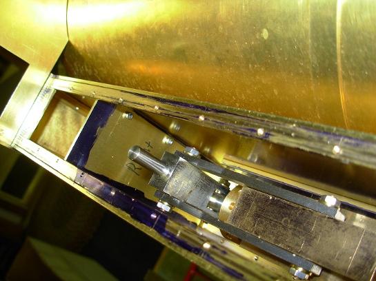
The water supply for the pump is on the bottom. These two fittings take the water into the pump.
I added a packing nut to the piston rod. It was not included in the drawing.